


-
26
-
-
27
-
8 MAINTENANCE
8 .11
Routine maintenance & service checks:
Every 6 & 12 months (see service log sheets below) the APU should be
inspected for:-
z
Damage to the electrical supply cable .
z
Damage to the inlet and outlet flexible hoses .
z
Leakage from the APU or the connecting pipework .
z
Controller log check; fault codes, pump run times, etc .
z
Test unit operation
z
Float valve check
z
Level probe check
z
Water condition check
z
Expansion vessel pre-charge check
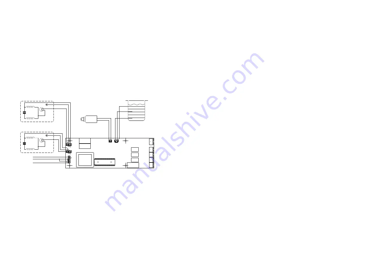
8 .12
Wiring diagram
There are no user servicable wiring or components inside the controller
assembly .
DO NOT remove the retaining screws or the membrane cover over
the display .
8 .13
Spares
The APU Midi is designed and built to be a reliable and high quality product,
in the event of spares being required, please contact the ADEY Customer Services
team on +44 (0) 1242 546 717 .
8 .14
Long term isolation and restart procedure
If the system is to be shut down for an extended period of time due to
maintainance or system modifications being carried out to the system the
following steps must be taken .
1 . Isolate mains inlet water from the APU Midi .
2 . Isolate the APU Midi from the system and vent excess pressure to drain .
3 . Run the APU to pump excess water from the tank to drain .
4 . Isolate the electrical supply from the APU .
5 . Remove the vent screws on the front of the pumps and allow excess
water to drain . Replace vent screws . See section 6 .26 .
6 .
Ensure the pressurisation unit cannot freeze . Damage will occur to the pumps
if this is allowed to happen .
7 . Cover with plastic sheet or cardboard if work is to be conducted close to
the APU .
8 .15
Restart
To ensure the APU is in good working order after a prolonged period of
maintainance the following steps should be taken .
1 . Inspect the APU for signs of damage .
2 . Check APU tank for debris, remove debris and clean tank if needed . Debris
may cause damage to the pumps if it is allowed to be drawn in .
3 . Check pressure vessel pre charge pressures before the system pressure is
increased .
4 . Open the mains water isolating valve allowing the APU tank to fill, and
ensure the fill valve is operating correctly and maintaining the correct
water level .
5 . Check for signs of leakage .
6 . Open the drain valve on the outlet of the APU .
7 . Turn on the mains electrical power and ensure both (if fitted) pumps can
run (use test pump option if needed) and are pumping water to drain .
8 . Close the drain valve and allow the APU to build pressure; the pressurisation unit
should turn off as the isolation valve to the system is closed .
9 . Open the APU outlet isolation valve and monitor the APU to ensure there are
no leaks as the system pressure increases .
10 . Check all the pre set values on the APU to ensure they are still suitable for
the system (after maintainance/modification)
9 ENVIRONMENT PROTECTION
Your appliance contains valuable materials which can be recovered or recycled .
At the end of the product’s useful life, please leave it at an appropriate local civic waste
collection point .
230 VAC/1PH/50Hz
SUPPLY
N
E
L
MAIN WINDING
THERMOTRIP
START WINDING
BLUE
BROWN
MOTOR 2
THERMOTRIP
BLUE
BROWN
MOTOR 1
PRESSURE TRANSDUCER
4-20mA, 0 - 10 bar
COMMON
LOW LEVEL
HIGH LEVEL
GREEN/YELLOW
GREEN/YELLOW
L E N
L E N
VO
LT
F
RE
E
AL
AR
M
CO
NT
AC
TS
-
5
AM
P
MA
X.
RS 485 modbus
LOW PRESSURE ALARM N/O
HIGH PRESSURE ALARM N/O
BOILER INTERLOCK N/O
COMMON ALARM N/O
GREEN/YELLOW
BLUE
BROWN
RED
GR
EE
N
BLUE
C L1 L2
- +
CAPACITOR
BLA
CK
BLU
E
MAIN WINDING
START WINDING
CAPACITOR
BL
AC
K
BLUE
2
1
BR
OWN
BLUE
TANK
1
2
3
4
Fig. 25
Содержание CP1-03-04913
Страница 1: ...Installation and servicing Midi 135 150 235 250 Digital Pressurisation Unit...
Страница 18: ...34...


