06-06-V6-smn
p6
TX
R
X
BUS RS485
NAME
+ Vcc
GND
A
TX+ et RX+
B
TX- et RX-
+
-
RX
TX
INHIB
RTS
CTS
TX+
TX-
RX+
RX-
jumper
TX- and RX-
connected together
by the U SER
TX+ and RX+
connected together
by the U SER
PCB revision A
AR
F7120
/A
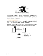
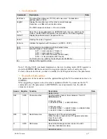
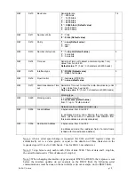
Figure 2: RS485 wiring, PCB marked ARF7120/A
The wiring could be checked by sending the SLI command using a terminal (see serial
command). If the link is properly configured, the modem register values are sent back by
the modem to the terminal (if not try to reverse the RS485 bus polarity
Î
reverse
RX+/TX+ with RX-/TX- connection).
•
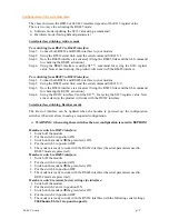
RS485 interface activation
When delivered the product is configured in RS232
Î
for
ACTIVATING
the RS485
interface, please refer to chapt.
Configuration of the serial interface
WARNING
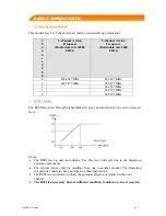
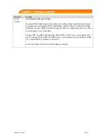
: when using the RS485 interface, the minimum time for switching from
RS485 transmission to RS485 reception is 4 ms, 20 ms for baudrate 600 and 1200bps.
ANSWER
data bytes
QUERY
data bytes
ARF
35
PC or
PLC
RS485 link
The delay between the
LAST byte of the query
and the first byte of the
answer MUST BE
GREATER than 4 ms


