31
208210A_UG_V1.6_ARFx3-PRO
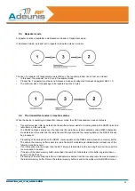
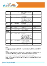
3.3. RS485 wiring
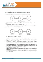
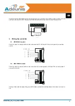
Wiring the RS485 bus only requires two cables:
•
TX+ is connected to RX+.
•
TX- is connected to RX- on the PCB.
BUS RS485 NAME
+ Vcc
GND
A
TX+/RX+
B
TX-/ RX-
+
-
RX
TX
INHIB
RTS
CT
S
TX+
TX-
RX+
RX-
Connect only TX-
or RX- (note 1)
Connect only
TX+ or RX+ (note
1)
Note 1:
TX- is connected to RX- on the PCB
TX+ is connected to RX+ on the PCB
ON
1 2
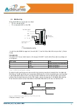
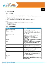
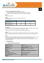
In order to enable RS485 management, the switch SW 1.1 must be ON and the S215 value must be 1 (cf table
below).
PLEASE NOTE
The switch SW1.1 is only read at power on. No change to the SW1.1 switch (while the modem is operating) will
be recognised.
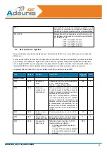
S215 value
SW1.1
Note
1
ON
RS485 command line management
1
OFF
RS232 configuration
0
ignored
RS232 configuration
Table 1: R485/232 configuration settings
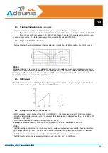
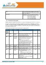
By default, the DE and RE lines are declared LOW, thus permitting reception of characters from the RS485 dif-
ferential bus. The DE and RE lines are only declared HIGH when one or more characters need to be transmitted
by the RS485 differential bus: when a radio frame is demodulated, the lines are declared HIGH, then the data
extracted from the radio frame is sent to the TXD module, and as a consequence to the RS485 differential bus.
When the last character has been transmitted on the RS485 differential bus, the lines are declared LOW.
TXD
RE/DE
Tde
Data
Threshold
1µs
Figure 1: DE/RE timing when data is sent over the serial link
Threshold: minimum = 1 µs
Содержание ARF33-PRO
Страница 7: ...6 208210A_UG_V1 6_ARFx3 PRO FRANCAIS ...
Страница 28: ...27 208210A_UG_V1 6_ARFx3 PRO ENGLISH ...
Страница 48: ...47 208210A_UG_V1 6_ARFx3 PRO DEUTSCH ...
Страница 69: ...68 208210A_UG_V1 6_ARFx3 PRO ITALIANO ...
Страница 89: ...88 208210A_UG_V1 6_ARFx3 PRO ESPAÑOL ...

