background image

AVR30 (E) QR33851

4

ENGLISH

12

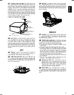
Outdoor Antenna Grounding—If an outside antenna or
cable system is connected to the video product, be sure

the antenna or cable system is grounded so as to provide
some protection against voltage surges and built-up static
charges.  Section 810 of the National Electrical Code,
ANSI/NFPA No. 70, provides information with respect to
proper grounding of the mast and supporting structure,
grounding of the lead-in wire to an antenna discharge unit,
size of grounding conductors, location of antenna-discharge
unit, connection to grounding electrodes, and requirements
for the grounding electrode.  See example below.

EXAMPLE OF ANTENNA GROUNDING

13

Power Lines—An outside antenna system should not
be located in the vicinity of overhead power lines or

other electric light or power circuits, or where it can fall into
such power lines or circuits.  When installing an outside
antenna system, extreme care should be taken to keep from
touching or approaching such power lines or circuits as con-
tact with them might be fatal.  Installing an outdoor antenna
can be hazardous and should be left to a professional antenna
installer.

USE

14

Cleaning—Unplug this video product from the wall out-
let before cleaning.  Do not use liquid cleaners or

aerosol cleaners.  Use a damp cloth for cleaning.

15

Object and Liquid Entry—Never push objects of any
kind into this video product through openings as they

may touch dangerous voltage points or short-out parts that
could result in a fire or electric shock.  Never spill liquid of any
kind on the video product.

16

Lightning—For added protection for this video product
during a lightning storm, or when it is left unattended

and unused for long periods of time, unplug it from the wall
outlet and disconnect the antenna or cable-system.  This will
prevent damage to the video product due to lightning and
power-line surges.

SERVICE

17

Servicing—Do not attempt to service this video product
yourself as opening or removing covers may expose

you to dangerous voltage or other hazards.  Refer all servicing
to qualified service personnel.

18

Conditions Requiring Service—Unplug this video prod-
uct from the wall outlet and refer servicing to qualified

service personnel under the following conditions.
a. When the power-supply cord or plug is damaged.
b. If liquid has been spilled, or objects have fallen into the

video product.

c. If the video product has been exposed to rain or water.
d. If the video product does not operate normally by following

the operating instructions.  Adjust only those controls that
are covered by the operating instructions.  Improper
adjustment of other controls may result in damage and will
often require extensive work by a qualified technician to
restore the video product to its normal operation.

e. If the video product has been dropped or the cabinet has

been damaged.

f. When the video product exhibits a distinct change in per-

formance — this indicates a need for service.

19

Replacement Parts—When replacement parts are
required, have the service technician verify that the
replacements he uses have the same safety charac-
teristics as the original parts.  Use of replacements
specified by the video product manufacturer can pre-
vent fire, electric shock or other hazards.

20

Safety Check—Upon completion of any service or
repairs to this video product, ask the service technician

to perform safety checks recommended by the manufacturer
to determine that the video product is in safe operating con-
dition.

ANTENNA
LEAD IN WIRE

GROUND CLAMP

ANTENNA
DISCHARGE UNIT
(NEC SECTION 810-20)

GROUNDING CONDUCTORS
(NEC SECTION 810-21)

GROUND CLAMPS

POWER SERVICE GROUNDING
ELECTRODE SYSTEM
(NEC ART 250, PART H)

ELECTRIC SERVICE
EQUIPMENT

NEC

 — NATIONAL ELECTRICAL CODE

Содержание AVR30

Страница 1: ...tely Mode d emploi Des performances optimales et un fonctionnement long terme seront assur s en appliquant les pr sentes instructions apr s avoir enti rement lu ce mode d emploi Manual de instruccione...

Страница 2: ...he recorder is received the unit must be connected to power source for 48 hours to assure the battery has been ad equately charged FOR YOUR SAFETY 2 PRECAUTIONS 2 IMPORTANT SAFEGUARDS 3 CONTROLS AND F...

Страница 3: ...for a log period and it is not intended to use the unit it is rec ommended that the unit be completely switched off by removing the plug Illustrated below is molded on the back of your unit CAUTION TO...

Страница 4: ...ots and openings in the cabinet are pro vided for ventilation to ensure reliable operation of the video product and to protect it from overheating These openings must not be blocked or covered The ope...

Страница 5: ...a or cable system This will prevent damage to the video product due to lightning and power line surges SERVICE 17 Servicing Do not attempt to service this video product yourself as opening or removing...

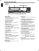
Страница 6: ...h the UP DOWN buttons 10 DOWN BUTTON Press to decrement change or reverse to the previous lower value 11 UP BUTTON Press to increase change or advance to the next higher value 12 V POS VERTICAL POSITI...

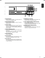
Страница 7: ...TIME FUNCTION on page 14 for details 23 RECORD BUTTON Press to start recording 24 STOP BUTTON Press to stop the tape The STOP button must be pressed to end the RECORD and PLAY mode 25 PLAY BUTTON Pre...

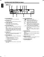
Страница 8: ...in the following cases A cassette is not loaded A cassette without its safety tab is loaded The timer has not been programmed 35 LOCK INDICATOR LOCK appears when the recorder is in the security lock...

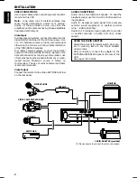
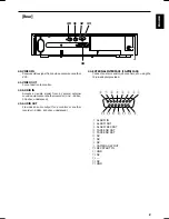
Страница 9: ...other recorder Line 8 dBm 50 Kohm unbalanced 43 AUDIO OUT Provides an audio output for a monitor or another recorder 9 dBm 600 ohm unbalanced 44 EXTERNAL INTERFACE 15 PIN JACK Connect an alarm switch...

Страница 10: ...t the switcher output to the Video IN BNC terminal Because mul tiple camera systems require synchronization use of cameras having line locked vertical sync or a gen locked master drive sync source is...

Страница 11: ...ND RE REC in the RECYCLE FUNC TIONS menu in the ALARM SET display or you have selected REWIND STOP IF ALARM and no alarm recording has been made The output impedance is approx 100 ohm TAPE END RST The...

Страница 12: ...when the safety tab is removed Notes The TAB indicator lights when a cassette without its safety tab is loaded To record again on a cassette that has its safety tab removed cover the tab hole with ta...

Страница 13: ...appears on the monitor screen when the power cord is first plugged in SELECTING A FUNCTION TO BE PROGRAMMED The program menu will always begin with the CLOCK SET function followed by the TIMER SELECTI...

Страница 14: ...12 Press the START STOP button the seconds will start counting and the clock will start CLOCK SET will flash on off again at this time 13 To display the time date you have set here on the monitor scr...

Страница 15: ...bove buttons Note Summer time cannot be set unless TIME DATE is displayed 1 Press the START STOP button twice so that OPTIONS flashes on off 2 Press the SET button so that the OSD TYPE set ting flashe...

Страница 16: ...tor 15 Press the SET button The other program event location of MON flashes on off 16 Press the UP or DOWN button until the desired program number appears on the monitor Notes If you do not need to ti...

Страница 17: ...me start time the program number with the longest stop time has priority To correct information 1 Press the START STOP button 2 Press the UP or DOWN button repeatedly until the item to be corrected Pr...

Страница 18: ...hich pulses are output to switch the camera 18 The pulses are output during recording at 18 or a longer speed ALL The pulses are output during recording in all modes 06 ONLY The pulses are output duri...

Страница 19: ...keep sounding if recording is abnormal Buzzer will not sound even if recording is abnormal ALARM OUT ON or OFF To specify whether buzzer turns on or off when alarm is output ON OFF Buzzer will keep s...

Страница 20: ...ot operate 1 Press the START STOP button The duration set ting flashes on off 2 Press the UP or DOWN button until the desired setting appears on the monitor MANUAL 5 15 30 SEC 1 3 5 10 30 60 MIN TAPE...

Страница 21: ...s press the ALARM RESET button to clear the ALARM memory Notes When the ALARM RESET button is pressed once if PL is flashing PL will disappear Press the button again to clear the ALARM memory When PL...

Страница 22: ...ures are being recorded normally or not during recording When the PLAY button is pressed during recording the recorded picture is played back for several sec onds Then recording will continue AUTO REC...

Страница 23: ...ate the ALARM recording in the stop mode follow the TAPE RECORDING procedure step 1 then select YES of the ALARM READY menu in the ALARM SET display MASTER SYSTEM RESET Press the two reset buttons sim...

Страница 24: ...button again to resume normal playback Notes The visual search speed can be changed using the SELECTION MENU screen The playback picture will have some noise in the visual search mode ALARM INDEX SEAR...

Страница 25: ...e TRACKING control may need to be returned to center position if previously adjusted The TRACKING control is only active at the 06 A18 or A30 speed Replace cassette Clean video heads Remove cassette a...

Страница 26: ...Output 1 Vp p 75 ohm unbalanced BNC S N Ratio Video More than 42 dB 06 mode S N Ratio Audio More than 40 dB 06 mode Horizontal Resolution Colour 300 lines 06 mode Monochrome 350 lines 06 mode Audio I...

Страница 27: ...26 ENGLISH...
Страница 28: ...asco Milano Italy 39 02 4571791 ADEMCO Sontrix Espana Vivero 5 28040 Madrid Spain 34 91 533 4706 Security House Amperestraat 41 1446 TR Purmerend Netherlands 31 299 419 000 Video Controls Ltd Aston Fi...

Отзывы: