


www.adeept.com
30
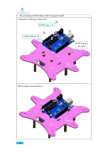
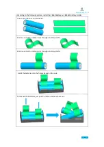
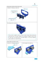
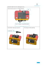
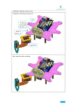
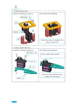
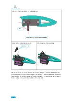
E. Take component C1 and component D1 and connect the steering gear to Adeept 32 Channel
PWM Drive.
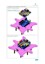
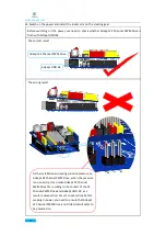
At this time, the steering gear and Adeept 32 Channel
PWM Drive have been installed. For convenience of
reading, only the wiring of the steering gear and Adeept
32 Channel PWM Drive are shown here.
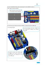
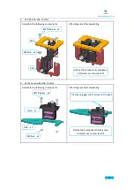
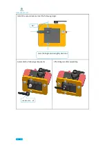
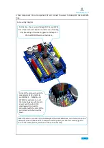
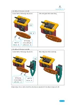
Servo wiring diagram
Connect the wiring of steering gear
on the components C1 and D1 to
PWM15 , PWM14, PWM13
respectively, The three servos and
three ports can be connected at will,
but the color of the servo line should
correspond to the port color, so as to
avoid the servo burning out.
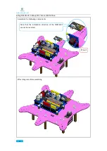
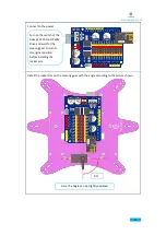
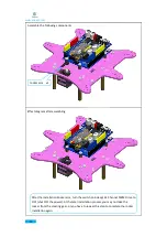
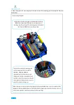
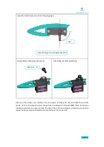
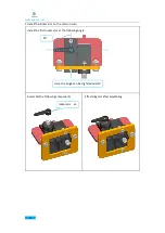
When the servo is connected to the Adeept 32 Channel PWM Drive, turn the switch of the
Adeept 32 Channel PWM Drive to "ON" (turn ON the power),and wait for the servo to turn
to the initial position, and then continue to the next step.
Содержание Hexapod 6 Legs Spider Robot
Страница 1: ...www adeept com 1...
Страница 40: ...www adeept com 36 The effect diagram after the assembly of three right feet...
Страница 49: ...www adeept com 45 The effect diagram after the assembly of three left feet...
Страница 63: ...www adeept com 59 C Connect Adeept Ultrasonic Module with Adeept 32 Channel PWM Drive...
Страница 64: ...www adeept com 60 D Connect Adeept RGB LED Module with Adeept 32 Channel PWM Drive...
Страница 65: ...www adeept com 61 E Connect Adeept Passive Buzzer Module with Adeept 32 Channel PWM Drive...
Страница 66: ...www adeept com 62 F Connect 18650x2 Battery Holder with Adeept 32 Channel PWM Drive...
Страница 67: ...www adeept com 63 G Connect 18650x2 Battery Holder with Adeept Remote Control Shield...
Страница 75: ...www adeept com 71...
Страница 77: ...www adeept com 73...
Страница 79: ...www adeept com 75 Click the button to upload the sketch to the board...
Страница 83: ...www adeept com 79...


