background image



























7

5V

2A

US

ER

CO

NS

OL

E

OP

TIO

NS

Connections

Connections do not need to be carried out in the order given within this guide, 

however, where possible connect the 

power in

 as a final step.

User console

The ports that make up the user console are where you attach the peripherals 
that will be shared between the computer systems. Ensure that power is 
disconnected from the unit. 

To connect peripherals to the user console

1  Position your peripheral devices in the vicinity of the unit such that their 

cables will easily reach.

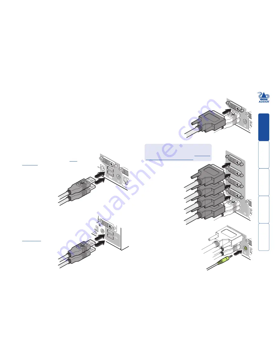
Keyboard and mouse

: Attach the leads from your USB keyboard and 

mouse to the USB sockets specifically labelled 
with keyboard and mouse symbols. The 
keyboard and mouse will operate in 
any of the USB sockets, however, 

True 

Emulation

 is not available on sockets 

labelled USB1 or USB2.

From 
speakers

Video monitor(s)

: DVI-I (integrated) video ports are 

used throughout to allow digital DVI and/or VGA 
analogue (via adapter cables) signals to be 
switched, as required.   

From USB keyboard and mouse

Audio

: Where required, connect the lead 

from your speakers to the audio socket.  

Note: The unit’s 

True Emulation


feature will read the full 
characteristics of the keyboard 
and mouse and will present 
those to each connected 
computer concurrently. 
This ensures 
that specialist 
keyboards and 
mice are fully 
supported.


From video 
monitor

5V

2A

US

ER

CO

NS

OL

E

OP

T

5V

2A

US

ER

CO

NS

OL

E

OP

T

1

USB

2.0

SWIT

CHE

D

USB

 1

USB

 2

USB devices

: Where required, attach the leads 

from your USB peripherals to the USB sockets 

labelled USB1 and USB2.

Note: These sockets provide 

enumerated

 (transparent) 

switching.

From USB peripherals

5V

4A

OP

T

US

ER

CO

NS

OL

E

4

3

2

1


Single screen units:

 Attach the 

lead from the video monitor 
to the DVI-I connector of 
the user console area. 

  Multiscreen units:

 Attach 

the lead from each 
video monitor to a DVI-I 
connector of the user 
console area.


Note: On the rear 
panel of the unit, the 
connectors at each 
horizontal level (V1 to V4) 
will be switched through 
to the user console DVI-I 
connector which is at the 
same level. 


From video 
monitors

  During initial power up, the AV4PRO-DVI unit 

will attempt to read the EDID information 
from the connected display(s). See 

Managing 

EDID video display information

 for details.

Содержание AV4PRO-DVI

Страница 1: ...AV4PRO DVI User Guide COMPUTER KVM SPK USB1 USB2 MODE www adder com AV4PRO DVI AV4PRO DVI DUAL AV4PRO DVI TRIPLE AV4PRO DVI QUAD ...

Страница 2: ...ion Using the configuration menu 13 General configuration 14 Changing hotkeys 14 Mouse switching 14 OPTIONS port speed 14 OPTIONS port channel control behaviour 14 Switching mode 15 Miscellaneous functions 15 Performing upgrades 16 Operation Selecting a computer 18 To select a computer using the front panel 18 To select a computer using hotkeys 19 To select a computer using the mouse buttons 20 To...

Страница 3: ... units feature True Emulation which ensures that the full characteristics of the connected keyboard and mouse are passed to every system Digital and analogue video The AV4PRO DVI units use DVI I Integrated connectors throughout so that DVI digital and or VGA analogue video may be used the latter requires the use of suitable adapter cables Multiple switching The attached peripheral devices can be s...

Страница 4: ... necessary signals states and processes Therefore manufacturers have previously relied upon a fixed keyboard and mouse profile that is declared to each computer regardless of the actual connected devices This precluded the use of any special keyboard or mouse features over and above the standard layouts True Emulation Mindful of the limitations associated with the previous USB switching techniques...

Страница 5: ...two USB devices to these connectors These ports are switched in an enumerated manner see What is True Emulation COMPUTER KVM SPK USB1 USB2 MODE www adder com Indicators The four indicators KVM SPK USB1 USB2 show which peripherals are switched to the current computer channel OR as you begin pressing the MODE button the peripherals that will be switched during the next press es of the COMPUTER butto...

Страница 6: ...pecific power lead Two 19 rack mount brackets and four screws Part number RMK3 Combined dual link DVI D and USB USB type A to B cable Part numbers VSCD3 2m length VSCD4 5m length Audio cable 2m 3 5mm stereo jacks Part number VSC22 DVI to VGA adaptor Part number VSA11 Single link DVI D to DVI D video cable Part number VSCD1 ww w a dder com 4 3 2 1 AD DER RC4 remote control plus standard 3m patch le...

Страница 7: ...l brackets plus four screws allow the unit to be secured within a standard rack slot Note Both the AV4PRO DVI unit and its power supply generate heat when in operation and will become warm to the touch Do not enclose them or place them in locations where air cannot circulate to cool the equipment Do not operate the equipment in ambient temperatures exceeding 40 degrees Centigrade Do not place the ...

Страница 8: ...Audio Where required connect the lead from your speakers to the audio socket Note The unit s True Emulation feature will read the full characteristics of the keyboard and mouse and will present those to each connected computer concurrently This ensures that specialist keyboards and mice are fully supported From video monitor 5V 2A USER CONSOLE OPT 5V 2A USER CONSOLE OPT 1 USB2 0 SWITCHED USB 1 USB...

Страница 9: ...king computers to the AV4PRO DVI unit Part numbers VSCD3 for a 2m cable and VSCD4 for a 5m cable From the USB port on the computer From the video port on the computer From the speaker port on the computer 2 1 USB2 0 SWITCHED USB 1 USB 2 2 1 USB2 0 SWITCHED USB 1 USB 2 1 USB2 0 SWITCHED USB 1 USB 2 V1 V2 V3 V4 4 3 2 1 Multiscreen units Use DVI or VGA to DVI I adapter cables if using analogue signal...

Страница 10: ...e them or place them in locations where air cannot circulate to cool the equipment Do not operate the equipment in ambient temperatures exceeding 40 degrees Centigrade Do not place the products in contact with equipment whose surface temperature exceeds 40 degrees Centigrade 5V 2A USER CONSOLE OPTIO Optional RC4 remote control The optional RC4 remote control unit full part number RC4 8P8C can be u...

Страница 11: ...rred are determined by the current setting of the switching mode Control by channel select input lines Where the external control is via the four channel select input lines of the OPTIONS port see pin out opposite ensure that the configuration menu option is set to to enable the input lines The four input lines are suitable for connection to dry contacts or open collector style outputs Connecting ...

Страница 12: ...r to switch up to eight video heads simultaneously Whenever an AV4PRO DVI channel is switched it sends an RS232 command out on its serial interface marked OPTIONS on the rear panel An AV4PRO DVI will switch its channel if it receives the same command on its serial interface Consequently by linking the serial interfaces a master unit may be made to automatically switch one or more slave units as sh...

Страница 13: ...nvoke this option the unit will only use the EDID information that it has already stored and pass this on to the connected computers To revert to interrogating the video display use the F 2 function discussed above To use the stored EDID information at the power up 1 Enter the Configuration menu 2 Press to enter the Functions menu 3 Press and then 4 Press and then to exit the menu Hybrid DDC suppo...

Страница 14: ...unctions menu Show current firmware version Refresh EDID information from the connected video display default Use the stored EDID at startup do not interrogate the video display Reset configuration to factory defaults is displayed momentarily Enter the Hotkey menu Ctrl Alt default Alt Ctrl Shift Left Ctrl Alt Alt Shift Right Ctrl Alt Right Alt Hotkeys disabled Enter the Options port behaviour menu...

Страница 15: ...hanges OPTIONS port channel control behaviour You can determine how the OPTIONS port responds to channel control inputs To define the OPTIONS port behaviour 1 Enter the Configuration menu 2 Press to enter the Options port menu and then press either to allow channel switching commands to be received via RS 232 serial signal through the OPTIONS port see Appendix 2 for cable pin out details and Chann...

Страница 16: ...the Configuration menu 2 Press to enter the Functions menu 3 Press and then 4 Press and then to exit the menu and save changes To use the stored EDID information at the power up When you engage this mode the unit will not interrogate the video display during startup and will instead use the data that are stored To revert to interrogating the video display use the F 2 function discussed above 1 Ent...

Страница 17: ... the power supply plug from the rear panel of the unit 3 Connect the upgrade computer to the AV4PRO DVI unit Connect the serial port of the upgrade computer to the OPTIONS port on the rear panel of the unit using the optional upgrade cable 4 Invoke upgrade mode While powering on or when already powered Press and hold the COMPUTER and MODE buttons for up to ten seconds until the numeric indicator s...

Страница 18: ...e dialog IMPORTANT Check that the Intended Target Units field matches the Unit Connected field If these fields do not match then you may have an incorrect upgrade file check with Adder Technology Ltd before proceeding Check also that the New firmware version is greater than the Current firmware version Check that the Intended Target Units field matches the Unit Connected field Check also that the ...

Страница 19: ... the keyboard video and mouse Will switch only the speakers Will switch only USB peripheral 1 Will switch only USB peripheral 2 Note If an indicator flashes it signifies that the respective peripheral is currently switched to another computer channel 2 Press the COMPUTER button repeatedly to select the required computer channel COMPUTER KVM V1 SPK V2 USB1 V3 USB2 V4 MODE Use this button to choose ...

Страница 20: ...l to the AV4PRO DVI unit that you wish to control it rather than the computer However if these particular hotkeys clash with another device or program you can change them to a different combination within the Configuration menu Additional hotkey press combinations In addition to the standard hotkey press combinations shown left you can also add additional keypresses in order to determine which per...

Страница 21: ...s reached release the middle button When using this method of switching The computer channels that are visited depend upon the configuration menu setting see note The ports KVM audio and or USB that are switched using this method depend upon the switching mode that is currently set using the front panel buttons Choosing which computers are accessed when using mouse buttons The computer channels th...

Страница 22: ... case sensitive and can be any combination of key strokes including the function keys but excluding the Num Lock Caps Lock Scroll Lock and keys If your keyboard has special media keys these also cannot be used as part of the password When you have typed in your password press to store it Don t worry if you type the password incorrectly you can always re enter configure mode and set the password ag...

Страница 23: ...puter ranging from 2 seconds to 5 minutes To prepare the autoscan period choose and then to within the configuration menu see right To start autoscanning mode press on the keyboard To select an autoscan mode 1 Enter the Configuration menu 2 Press and then press either 7 to choose Cycle all ports or 8 to choose Cycle only active ports 3 Press to accept the setting and return to the main menu sectio...

Страница 24: ...cking the information contained within this guide then we provide a number of other solutions Online solutions and updates www adder com support Check the Support section of the adder com website for the latest solutions and firmware updates Adder Forum forum adder com Use our forum to access FAQs and discussions Technical support www adder com contact support form For technical support use the co...

Страница 25: ... VGA 720 x 400p at 88Hz IBM XGA2 640 x 480p at 60Hz IBM VGA 640 x 480p at 67Hz Apple Mac II 640 x 480p at 72Hz VESA 640 x 480p at 75Hz VESA 800 x 600p at 56Hz VESA 800 x 600p at 60Hz VESA 800 x 600p at 72Hz VESA 800 x 600p at 75Hz VESA 832 x 624p at 75Hz Apple Mac II 1024 x 768i at 87Hz IBM 1024 x 768p at 60Hz VESA 1024 x 768p at 70Hz VESA 1024 x 768p at 75Hz VESA 1280 x 1024p at 75Hz VESA 1152 x ...

Страница 26: ... both types of connector Serial remote control and flash upgrade cable 8p8c 8p8c connector D Type female 9 way Multi head synchronisation cable 8p8c MASTER end 8p8c connector SLAVE end 8p8c connector 6 2 TXD RXD 3 2 3 5 RXD GND TXD GND Serial remote control and flash upgrade cable 10p10c 10p10c connector D Type female 9 way 7 2 TXD RXD 4 3 3 5 RXD GND TXD GND 7 4 TXD RXD 3 3 GND GND Multi head syn...

Страница 27: ...VI unit make sure the total ampere rating of the devices plugged into the extension cord does not exceed the cord s ampere rating Also make sure that the total ampere rating of all the devices plugged into the wall outlet does not exceed the wall outlet s ampere rating Do not attempt to service the AV4PRO DVI unit yourself Warranty Adder Technology Ltd warrants that this product shall be free from...

Страница 28: ...r is connected d Consult the supplier or an experienced radio TV technician for help FCC Compliance Statement United States This equipment generates uses and can radiate radio frequency energy and if not installed and used properly that is in strict accordance with the manufacturer s instructions may cause interference to radio communication It has been tested and found to comply with the limits f...

Страница 29: ...ww ctxd com Documentation by 2012 Adder Technology Limited All trademarks are acknowledged Part No MAN AV4PRO DVI Release 1 1b Web www adder com Contact www adder com contact details Support forum adder com ...

Страница 30: ...ltiple units synchronising 11 Multiple video head connections 11 O Operation 18 Options port 4 behaviour setting 14 pinout 10 speed setting 14 P Parts supplied and extra 5 Password setting entering 21 Peripherals connecting 7 R Rack mounting 6 Remote control by computer 10 14 by RC4 unit 9 Remote wakeup 2 RS 232 serial switching commands 10 S Safety information 26 Selecting computers with front pa...

Отзывы: