ADCA
VAL
S
TEAM
ADCA
We reserve the right to change the design and material of this product without notice.
IMI PV25G.20 E 04.16
Fig.2
– Reverse action actuator
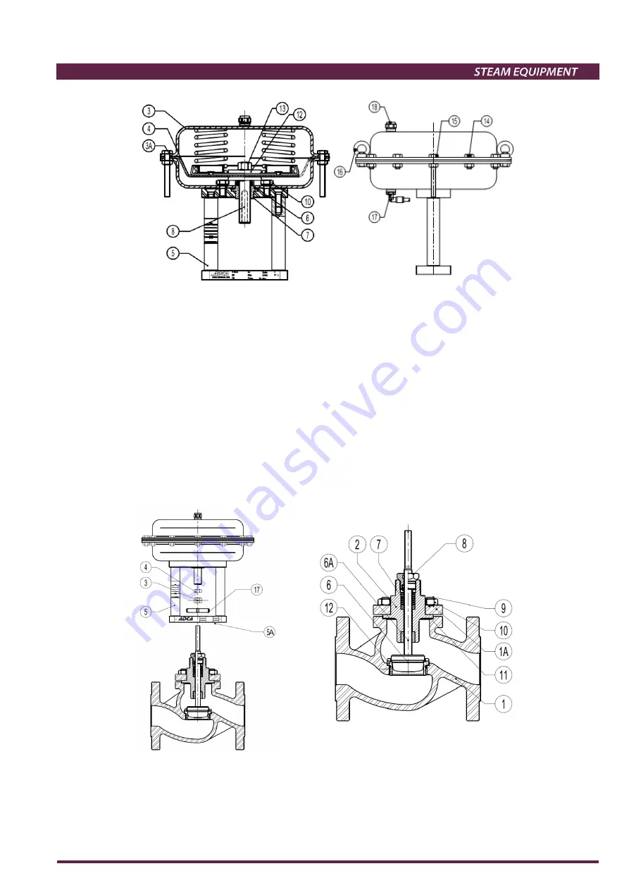
Removing actuator from valve:
In reference to the fig.3 proceed as follow:
1. Loosen the lock nuts (4).
2. Release air supply to the actuator and drive it into approximately mid-travel position.
3. Loosen the mounting nut (17) completely.
4. Reduce air supply pressure until housing is pressure free.
5. Check and measure the shifting between yoke base plate (5A) and flange valve body (1A) and take note.
6. Catch the actuator pillars and remove it from valve body. Nuts (10) can be used to fix the valve spindle in order
to avoid its rotation and consequently valve plug damage against the seat. Valve spindles are burnished and if
this super finishing is destroyed doing to the use of wrong tools packing will be consequently damage in a short
period of time.
7. Re-assemble all the items in reverse order ensuring the alignment of spindles and plug-seat consequently.
Fig.3 Fig.4


