background image

Initializing the Maintenance Terminal Screens


150-402-111-02

32

December 8, 1998

 HRU-402 List 1A

Table 8.

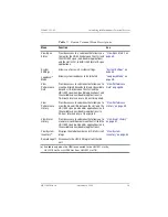
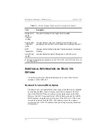
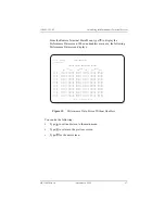
Span Status Fields and Descriptions

Field

Description

Time

Time of day when Span Status was checked.

Date

Date when Span Status was checked.

Alarms

Presence or absence of alarm conditions.

Loopback

Indicates Off condition or identifies specific active loopback. See

Table 10 on page 41

.

Power Level

Indicates the HDSL Power Feed voltage mode: High, Low, or Disabled.

Margins

Indicates the excess signal to noise ratio at all HDSL ports, relative to a 
10

-7

 Bit Error Rate, in xx/xx/xx format where:

First value is current margin.

Second value is minimum margin since last cleared. 

Third value is maximum margin since last cleared.

Pulse 
Attenuation

Indicates the attenuation of the 2B1Q pulse from the distant end. HiGain 
operates with pulse attenuations up to 28 dB. This value is related to the 
cable pair’s 196 kHz loss. The pulse attenuation is a more direct indication 
of the loop attenuation to the 2B1Q signal than the 196 kHz loss.

INS Loss

Indicates the approximate attenuation of the HDSL loop at 196 kHz. It is 
generated by multiplying the pulse attenuation by 1.25.

PPM Offset

Indicates the relative offset of the crystal oscillator in the HRU-402 from 
the HLUs crystal oscillator. Any value between ± 100 is adequate.

HDSL 24 
Hour ES

The number of one second intervals that contained at least one HDSL CRC 
error. This value is a running total of the last 24 Hours.

HDSL 24 
Hour UAS 

The number of seconds the HDSL loop was out of synchronization. This 
value is a running total of the last 24 Hours.

DS-1 
24-Hour BPV 
Seconds (ES)

The number of seconds in which at least one bipolar violation was 
detected on the DS-1 input. This value is a running total of the last 24 
Hours.

Continued

Содержание 150-1592-11

Страница 1: ...HRU 402 HiGain REM UNIT ALM L TELEPHONE Co PROPERTY LP2 ESF SF LP1 B8ZS AMI LBK H D S L R C V L E V D S 1 0 15 7 5 7 5 15 XMT BRG RCV RS 232 DCE BARCODE 1A HRU 402 List 1A Remote Unit Product Catalog...

Страница 2: ...respective companies Disclaimer of Liability Information contained in this document is company private to ADC DSL Systems Inc and shall not be modified used copied reproduced or disclosed in whole or...

Страница 3: ...extent of damage to the transportation company and to ADC DSL Systems Inc Order replacement equipment if necessary Check the packing list to ensure complete and accurate shipment of each listed item I...

Страница 4: ...Unpack and Inspect Your Shipment 150 402 111 02 iv December 8 1998 HRU 402 List 1A...

Страница 5: ...ions 11 HLU Front Panel Display Messages 12 Card edge Pinout Connector 15 Functional Description___________________________________ 16 Installation ____________________________________________ 18 Insp...

Страница 6: ...ck Operation 42 SmartJack Set to ENA 44 SAIS Set to DIS 44 Loopback Test Procedures 45 View Performance Data 46 View Performance History 49 View Alarm History 51 View System Inventory 54 Appendix A Sp...

Страница 7: ...System Spans 26 12 Remote Terminal Main Menu 28 13 View Span Status Screen for Non doubler Applications 30 14 Span 1 Status Screen for Doubler Applications 31 15 System Settings Screen 34 16 Loopback...

Страница 8: ...ED Descriptions 9 4 Rear Unit TLOS Switch 11 5 HLU Front Panel Display Messages 12 6 Maintenance Terminal Navigational Keys 27 7 Remote Terminal Menu Descriptions 29 8 Span Status Fields and Descripti...

Страница 9: ...a CSA range The HRU 402 List 1A is line powered only Figure 1 shows a basic HiGain configuration for a T1 High bit rate Digital Subscriber Line HDSL circuit The HLU is installed at the Central Office...

Страница 10: ...r loopback activation codes Line powered Lightning and power cross protection on HDSL and DS 1 interfaces 784 kbps full duplex 2 Binary 1 Quaternary 2B1Q HDSL transmission on each of two pairs Digital...

Страница 11: ...limitation and become BPVT transparent by detecting and counting input BPVTs at each end and then replicating them at the distant end T1 output port In addition the CRC errors in each direction of ev...

Страница 12: ...ear depending on the frequency of the transient errors This BER option is present in any HiGain 98 line unit circuit APPLICATIONS HRU 402 List 1A provides a cost effective and easy to deploy method fo...

Страница 13: ...rement data add 3 dB for each bridged tap and 1 dB for each cable gauge change COMPATIBILITY The HRU 402 List 1A can be used with all HiGain doublers and doubler compatible line units for two or three...

Страница 14: ...es indoor use HRE 420 single wide single mount HRE 422 double wide double mount HRE 425 12 slot wall or rack mount HRE 427 seven slot wall or rack mount 200 Mechanics type shelves 400 Mechanics type s...

Страница 15: ...arm LED Loopback LED CLEI ECI Bar code label Loopback control button DS 1 receive attenuation switches RS 232 Craft port Extraction handle DS 1 transmit and receive bridging jacks HDSL LEDs DS 1 frami...

Страница 16: ...above is set to 7 5 15 15 Sets the DS 1 receive level toward the CI to 15 dB if switch above is set to 7 5 15 DS 1 XMT and RCV Bridging jacks Provides bridging test and monitor access jacks to the CPE...

Страница 17: ...me per second Indicates the HDSL loop is trying to acquire sync Blinking green 4 times per second Indicates a margin alarm condition on the HDSL loop Blinking green 10 times per second Indicates a Cyc...

Страница 18: ...Inversion AMI or B8ZS This light blinks one time per second when a Bipolar Violation BPV is detected AMI LED Solid green DS 1 Code Option Auto b Indicates the DS 1 line code is being detected as AMI L...

Страница 19: ...n page 7 The RCV LEV options are defined in Table 2 on page 8 The TLOS switch adjacent to the card edge connector is shown in Figure 3 The TLOS options are defined in Table 4 Figure 3 TLOS Switch Loca...

Страница 20: ...nal from DSX is looped back to the DSX at the HRU by the HRU SmartJack TLOS TransmitLossOf Signal HRU is in a logic loopback state caused by a loss of its T1 input from the CI if enabled at the HRU by...

Страница 21: ...2 The third doubler and an HRU are trying to establish synchronization with each other on loops 1 or 2 of Span 4 H1ES HDSL CRC Error Channel 1 HLU HDSL Loop 1 CRC error H2ES HDSL CRC Error Channel 2...

Страница 22: ...button at the HLU for 3 or more seconds LIST 0xL HLU s List Displayed during System Settings review mode FRM Frame SF ESF UNFR NONE Defines the type of frame pattern being received from the DSX 1 Disp...

Страница 23: ...escription HRU 402 List 1A December 8 1998 15 CARD EDGE PINOUT CONNECTOR The HRU 402 occupies one slot in a remote enclosure The card edge pinout connector for the remote unit is shown in Figure 4 Fig...

Страница 24: ...Gain system A block diagram of the HRU 402 is shown in Figure 5 on page 17 The HRU 402 List 1A power supply converts the 90 to 200 Vdc power that is received on the simplex pairs to the voltage and cu...

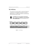
Страница 25: ...150 402 111 02 Functional Description HRU 402 List 1A December 8 1998 17 A block diagram of the HRU 402 is shown in Figure 5 Figure 5 HRU 402 Block Diagram...

Страница 26: ...the extent of damage to the transportation company and to ADC DSL Systems Inc Your shipment should consist of One HRU 402 HiGain Remote Unit user manual INSTALLING HRU 402 LIST 1A To install the HRU...

Страница 27: ...to the card edge connector until it is entirely within the card guide The unit should snap into place indicating that the unit is properly seated Remote enclosure HRU 402 HR U 4 02 HiG ain RE M UN IT...

Страница 28: ...power is lost or turned off CONNECTING TO A TERMINAL EMULATOR This section covers the remote terminal screens for both non doubler and doubler applications Once connected you can access the Remote Te...

Страница 29: ...9 and DB 25 of RS 232 I O interfaces on the maintenance terminals PCs 2 Once the serial cable is connected to the Craft port RS 232 DB 9 connector on the HRU 402 connect the other end of the cable to...

Страница 30: ...ty None 8 data bits 1 stop bit Hardware Flow Control set to None VT Terminal Emulation If you are using the Microsoft Windows terminal emulation program from the Settings Terminal Preference menu you...

Страница 31: ...s to its remote login mode if possible Once in a remote login mode it will remain there until something occurs that inhibits a remote login session Then it is forced to be a local login mode All line...

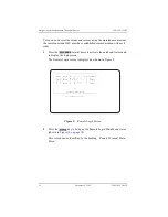
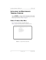
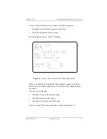
Страница 32: ...tobaud feature and to display the login screen The Remote Login screen is displayed as shown in Figure 9 Figure 9 Remote Login Screen 2 Press the key to bring up the Remote Login Main Menu screen show...

Страница 33: ...te login session at a time An active session at any module other than the HLU prohibits active sessions at all other circuit modules The HRU 402 automatically performs a remote logoff if no activity a...

Страница 34: ...f spans in a particular application Figure 11 is a graphical representation of system spans The HRU Maintenance Terminal menus allows the user to monitor multi span applications from the HLU to the HR...

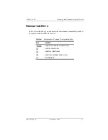
Страница 35: ...YS Table 6 describes keys you can use on the maintenance terminal keyboard to navigate within the HRU 402 menus Table 6 Maintenance Terminal Navigational Keys Key Function Logs into the Remote Termina...

Страница 36: ...initial Remote Login screen shown in Figure 9 on page 24 REMOTE TERMINAL MAIN MENU Figure 12 displays the Remote Terminal Main Menu and Table 7 on page 29 describes the function of each menu selection...

Страница 37: ...ow you to view the Errored Seconds ES and Unavailable Seconds UAS between the HLU and the HRU 402 span non doubler applications and the available spans doubler applications in 15 minute intervals over...

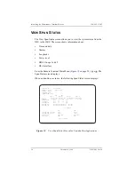
Страница 38: ...n use the following Span Status screen displays Figure 13 View Span Status Screen for Non doubler Applications TIME 00 14 11 SPAN STATUS DATE 02 02 98 CIRCUIT ID ALARMS NONE LOOPBACK OFF POWER LEVEL H...

Страница 39: ...owing Press to return to the previous menu Press to update current values Press to view the next available span Table 8 on page 32 describes each status item shown in Figure 14 TIME 00 14 11 SPAN 1 ST...

Страница 40: ...om the distant end HiGain operates with pulse attenuations up to 28 dB This value is related to the cable pair s 196 kHz loss The pulse attenuation is a more direct indication of the loop attenuation...

Страница 41: ...ZBTSI The latter two conditions indicate the code type that is being received when HiGain is set to its ZBTSI mode In either the AMI or B8ZS DS 1 code mode the selected code is displayed when in auto...

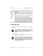
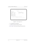
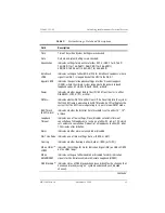
Страница 42: ...riptions SYSTEM SETTINGS TIME 03 40 57 DATE 10 04 98 CIRCUIT ID EQUALIZATION 0 MARGIN ALARM THRESH 4 SMART JACK LPBK ENABLED RLOS DS1 LOS ALARM ENABLED SPECIAL LPBK GNLB ALARM PATTERN AIS POWER AUTO B...

Страница 43: ...ing tells the system that the ESF frame is operating in its ZBTSI mode An Off setting tells the system that the ESF frame is operating in its normal non ZBTSI mode BER Thresh BERT Alarm Indicates whet...

Страница 44: ...ser of the LOS state LOS is sent towards the network from the HLU This option prevents the common occurrences of a CPE LOS condition from generating recurring alarms and AIS payloads Margin Alarm ALM...

Страница 45: ...payload during one of the above alarm conditions DS 1 Line Code Auto Option When the DS 1 line code option is set to AUTO mode both the HLU and HRU 402 set their T1 output codes to the codes received...

Страница 46: ...ocal T1 input code LOOPBACK MODE The Loopback Mode menu only appears if the HRU 402 is connected to an HLU 231 List 7B or List 8x HLU 319 List 5x HLU 388 List 5x All other HLU types do not allow loopb...

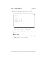
Страница 47: ...Without Doublers 2 Type to select the disable loopbacks option 3 Type to select HLU network loopback 4 Type to select HRU network loopback 5 Type to select HLU customer loopback 6 Type to select HRU...

Страница 48: ...o initiate a loopback Choose one of the options listed in Table 10 between through Type to exit and return to the previous menu LOOPBACK MENU TIME 00 03 33 DATE 02 02 98 CIRCUIT ID A DISABLE LOOPBACKS...

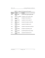
Страница 49: ...back Loopback at HRU local towards CI CREM Customer Remote Loopback Loopback at HLU remote towards CI NDU1 Network Doubler 1 Loopback Loopback at first doubler towards network CDU1 Customer Doubler 1...

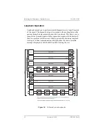
Страница 50: ...is returned to the sending device after passing through a data communications link or network This allows you to compare the returned signal with the transmitted signal and to determine if there is a...

Страница 51: ...e CPE during SmartJack or NREM loopbacks set the SAIS to ENA before the loopback is initiated Customer Local Loopback CLOC signal from CI is looped back to customer at HRU 402 Transmit Loss of Signal...

Страница 52: ...ctive This puts the HiGain system in its AIS ENA SmartJack loopback state It remains in this state until a loopdown command is detected or the default time out period if enabled expires When the HRU i...

Страница 53: ...ed by a LOS of T1 input at the HRU from the customer The HRU 402 front panel loopback button is used to initiate NREM and terminate an NREM loopback To initiate an NREM loopback at the HRU press the l...

Страница 54: ...and loop up NLOC for five seconds Verify that the HLU displays the message NLOC indicating that the HLU unit is in its network loopback state 6 Repeat Step 3 If the test passes the problem is in the c...

Страница 55: ...016 012 010 016 003 005 007 013 002 001 00 30 000 000 000 000 000 000 000 000 000 000 000 000 00 45 006 010 012 005 000 000 000 000 000 000 001 000 01 00 000 000 000 000 000 000 000 000 000 000 000 00...

Страница 56: ...DU1 HLU HDU1 00 00 000 000 000 000 000 000 000 000 000 000 000 000 00 15 000 000 016 012 010 016 003 005 007 013 002 001 00 30 000 000 000 000 000 000 000 000 000 000 000 000 00 45 006 010 012 005 000...

Страница 57: ...ications Figure 21 Figure 21 Performance History Screen for Non doubler Applications 2 Type to exit and return to the main menu Time 00 16 55 7 DAY HISTORY CIRCUIT ID ERRORED SECONDS UNAVAILABLE SECON...

Страница 58: ...SECONDS DS 1 HDSL 1 HDSL 2 HLUHRUHLU HDU1HLU HDU1 01 26 00000 00000 00000 00000 00000 00000 00000 00000 00000 00000 00000 00000 01 27 00000 00000 00000 00000 00000 00000 00000 00000 00000 00000 00000...

Страница 59: ...ry Screen for Non doubler Applications You can do one or more of the following Type to update the screen Type to exit the main menu ALARM HISTORY TIME 00 17 18 DATE 10 04 98 CIRCUIT ID Type First Last...

Страница 60: ...First and last instance of BER 10 7 or 10 6 threshold crossing current condition number of alarms Span1 LOSW HDSL1 First and last instance of LOSW on HDSL1 current condition number of alarms Span1 LOS...

Страница 61: ...doubler applications and the Span 4 Alarm History screen displays for 3 doubler applications The following options are available Type to exit and return to the main menu Type to update the values Type...

Страница 62: ...ning the data remains even when power is lost or turned off All six possible unit modules are always listed Those that have not been detected and are not present in the circuit are labeled Not Availab...

Страница 63: ...type to display the View System Inventory screen Figure 25 View System Inventory Screen 2 Type to exit and return to the previous menu SYSTEM INVENTORY TIME 03 49 22 DATE 10 04 98 CIRCUIT ID UNIT PROD...

Страница 64: ...cted to the following line units HLU 231 List 8x HLU 319 L5x and HLU 388 L5x 4 5 W when connected to all other line units Maximum provisioning loss 35 dB at 196 kHz 135 Electrical protection Secondary...

Страница 65: ...100 Pulse output 0 dB Receive Level REC LEV 0 7 5 db REC LEV 7 5 15 dB REC LEV 15 Input level sensitivity 22 5 dB Line rate 1 544 Mbps 200 bps System output wander looped 0 3 UI 648 ns max Line format...

Страница 66: ...ystem Turn Up and Testing Network Monitoring upstream or downstream Power Monitoring and Remote Surveillance Service Maintenance Agreements Systems Operation ADC Technical Assistance Center 800 638 00...

Страница 67: ...rican Wire Gauge B8ZS Bipolar with 8 zero Substitution BRG Bridged BER Bit Error Rate BERT Bit Error Rate Threshold BPV Bipolar Violation BPVT Bipolar Violation Transparency CI Customer Interface CO C...

Страница 68: ...Extended Super Frame Data Link FDL Facility Data Link HDSL High bit rate Digital Subscriber Line HDU HiGain Doubler Unit HLU HiGain Line Unit HRE HiGain Remote Enclosure HRU HiGain Remote Unit I CPE C...

Страница 69: ...C LEV Receive Level RLOS Remote Loss of Signal SAIS SmartJack AIS SF Super Frame SPLB Special Loopback TEC Total Error Count TSEC Total System Error Count TSGR Transport System Generic Requirements UA...

Страница 70: ...Appendix C Abbreviations 150 402 111 02 62 December 8 1998 HRU 402 List 1A...

Страница 71: ...ADC s option any such hardware product which is returned during the 12 month warranty period per ADC s instructions and which product is confirmed by ADC not to comply with the foregoing warranty ADC...

Страница 72: ...THAT SOFTWARE WILL BE FREE FROM BUGS OR THAT ITS USE WILL BE UNINTERRUPTED OR REGARDING THE USE OR THE RESULTS OF THE USE OF THE SOFTWARE IN TERMS OF CORRECTNESS ACCURACY RELIABILITY OR OTHERWISE MOD...

Страница 73: ......

Страница 74: ...klin Avenue Tustin CA 92780 7013 Tel 714 832 9922 Fax 714 832 9924 Technical Assistance Tel 800 638 0031 Tel 952 917 3222 Fax 714 730 2400 DNV Certification Inc REGISTERED FIRM ISO 9001 TL 9000 DOCUME...

Отзывы: