


Installation
150-450-132-02, Issue 02
8
March 6, 2000
HRE-450 List 2B, List 3B, and List 4B
W
IRING
THE
HRE-450 L
IST
2B
AND
L
IST
3B
The HRE-450 List 2B has a 20-foot gel-core stub. This stubs consists of a 6-pair, 24 AWG plastic-insulated,
single-jacketed, gel-core cable. The HRE-450 List 3B has a 20-foot air-core stub. Conductors are insulated with
solid high-density polyethylene. Standard color codes are used for pair identification with color compounds
chosen for electrical balance and permanency. A non-hygroscopic core wrap protects the core and provides
improved mechanical and electrical characteristics. The cable core shield is a corrugated copolymer coated 8 mil
aluminum tape. The outer jacket consists of a black, low-density polyethylene material that provides a flexible
protective covering that withstands exposure to sunlight, atmospheric temperatures, ground chemicals and stresses
expected in standard installations. The cable complies with the requirements of ANSI/ICEA S-85-625-1989 and
REA PE-22. The outside diameter of the cable is 0.36 inches (9 mm).
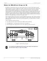
Figure 4
shows the identity of the four ports to which each cable stub provides access. The CO ports are restricted
to the CO HDSL cable pair connections that connect the HRE-450 to either a doubler or a line unit. The field pairs
connect to a downstream doubler or remote unit (for doubler applications), or to the DS1 interfaces (for remote
unit applications).
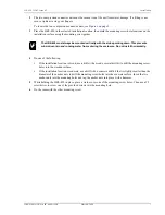
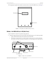
Connect the HRE-450 to ground as follows:
1
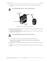
Feed solid ground wire, up to #6 AWG, through the HRE-450 GND cable fitting.
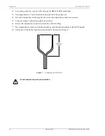
2
Strip approximately
1
/
2
-inch of insulation from the end of the ground wire.
3
Insert the stripped wire into the ground wire access, then tighten the ground wire connector.
Figure 4.
HRE-450 Wiring Diagram
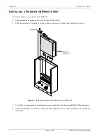
The connections to the HRE-450 List 4B (no stub) are made directly to the 4 Quiet Front
protectors shown in
Figure 2 on page 3
and in
Figure 4
.


