


A
LPHA
X
PRESS
2020 RGB F
RONT
A
CCESS
F
ULL
-M
ATRIX
D
ISPLAYS
S
IGN
O
PERATION
AND
M
AINTENANCE
M
ANUAL
(PN 1523610201
REV
.
B
)
3-3
Installation
3
E
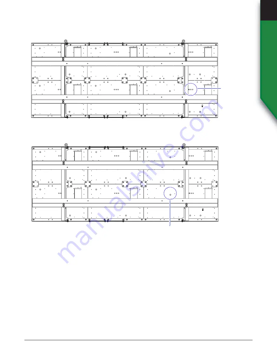
LECTRICAL
INSTALLATION
Light sensor
Plug the three light sensor cables into the light sensor ports on the back of the sign.
Network connection
Plug the Ethernet cable into the external waterproof port on the back of the sign.
Light sensor
ports
External waterproof IP67
Ethernet connection
Содержание AlphaXpress 2020
Страница 51: ......


