ENGLISH (translation of original instructions)
EN
E 220 - E 115 - E 12-24
Suction
Discharge
Pump inlet connection thread
3/4" G - BSP 3/4" G - BSP
Recommended minimum internal diameters
ø20 mm
ø20 mm
Recommended rated pressure
10 Bar
10 Bar
Pipe suitable for operation under negative pressure
•
5.3 - r
emarks
on
the
suctIon
lInes
SUCTION
LINE
The electric pumps in this manual are self-priming and can draw the liquid from a maximum height of 2
metres. Caution, proper priming and the time required for this can be affected by an automatic nozzle on
the discharge line, which prevents normal air extraction from the pipe. It is therefore always advisable to
prime the pump for the first time without the automatic nozzle and with the discharge pipe emptied from
the liquid. To facilitate the subsequent start-up operations of the pump so that they are immediate, it is
always recommended to install a foot valve to prevent the suction pipe from emptying and to keep the
pump wet. When the system is in operation, the pump can work with negative pressure at the suction
inlet up to 0.5 Bar, after which cavitation phenomena can start with consequent reduction of the flow rate
and increase in noise. To prevent this phenomenon from occurring it is important to ensure low suction
negative pressure, by using short pipes or pipes with a diameter larger than or the same as those recom
-
mended, minimising bends and using large section suction filters and foot valves with the least resistance
possible. Moreover, it is very important to keep all suction filters clean to prevent the system resistance
from increasing when they are clogged.
DISCHARGE
LINE
The electric pump must be chosen based on the system’s specifications. Incorrect combinations of the
length of the pipe, of its diameter, of the flow rate of the diesel fuel and/or of the accessories installed on
the line, can create a counterpressure on the discharge line that is higher than the maximum set and so
cause the pump bypass to open (partially) with consequent reduction in the flow rate dispensed. To pre
-
vent this from happening and allow the pump to work properly, the system resistance has to be reduced
using pipes that are shorter and/or with a larger diameter and line accessories with less resistance (e.g.
an automatic nozzle for greater flow rates).
5.4 - e
lectrIcal
connectIon
of
the
pump
E220 and
E115
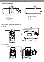
E 220 pumps are supplied without cover, with service switch, without safety fuse, 2 m cable.
E 12-24
E 12-24 pumps are supplied with service switch, safety fuse, 4 m cable and crocodile clips for connec
-
tion to the battery.
The fuse specifications are indicated for each model on its body and in the technical specifications
section (Chap. 2.3).
For proper installation and electrical maintenance of the system, please follow these instructions:
- make sure the power lines are not live when installing or carrying out maintenance operations on the system
- use cables with minimum section, rated voltages and type of installation suitable for the system’s
specifications
- always connect the pump’s earth terminal to the electricity grid’s earth line (E220 and E115 version)
- properly connect the device following the polarity (E 12-24 version)
CAUTION! The pumps are provided without safety devices such as fuses, motor protectors,
systems against accidental restart after a power failure. Even the switch, if any, will only start/
stop the pump and can in no way replace a suitable circuit breaker. It is therefore the direct
responsibility of the installer to connect the pump to the main electrical panel in compliance
with the regulations in force in the country of use.


