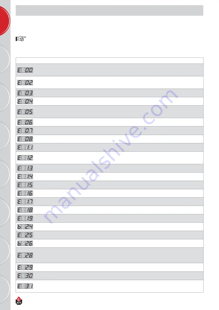
LIST OF ERROR CODES + SOLUTIONS
[in ERROR mode]
If a fault occurs during operation, the system locks out and the screen starts to flash.
The first character is an “E” or “b” and the following two indicate the code of this fault, as indicated in the table below.
To unlock the system:
• Press "RESET" on the screen.
• If the fault is repeated continually, contact your installer.
MCBA BLOCKAGE AND ERROR CODES
Codes
Description of the fault
Resolution of the fault
Abnormal flame signal detected
1. Check the wiring (short circuit in the 24 V wiring)
2. Check the electrode
3. Replace the MCBA (water damage)
No flame presence after five start-up attempts
1. Check the ignition wiring
2. Check the electrode and its position
3. Check the burner gas level
Gas valve or triac error
Replace the rectifier or the gas valve
Durable locking
Press “RESET”
No flame detection or poor feed current quality
1. Check the electrode gap
2. Check resistance kΩ of the electrode cable
3. Stabilisation of the current
Detection of an Input error
Check the Input and press “RESET”
Gas valve relay error
If the problem persists after two “RESET” attempts, replace the MCBA
The air pressure switch did not close
Check the air pressure switch
EPROM error
If the problem persists after two “RESET” attempts, replace the MCBA
Max input thermostat open or 24 V fuse has blown.
1. Check the limit thermostat
2. Check the 24 Volt fuse of the MCBA
3. Link 12-13 missing
Internal error
If the problem persists after two “RESET” attempts, replace the MCBA
Water in the 24 Volt circuit
Check the 24 Volt circuit and dry if necessary [sensors, terminal, etc.]
Internal error
If the problem persists after two “RESET” attempts, replace the MCBA
Internal error
If the problem persists after two “RESET” attempts, replace the MCBA
Internal error
If the problem persists after two “RESET” attempts, replace the MCBA
T1 > 110°C
1. Check the NTC wiring and replace it if necessary
2. If the NTC1 sensor is OK, check if there is water flow in the boiler
T2 > 110°C
Check the NTC wiring and replace it if necessary
The NTC1 and NTC2 sensors are the wrong way
round
Switch the NTC1 and NTC2 sensors around
T1 gradient too high
1. Check if the pump is running
2. If there is no problem with the pump, bleed the system
Gas pressure switch or low-water pressure switch
open
Check the gas pressure switch or the low-water pressure switch
No tachometer signal from the fan
1. Check the PWM connection
2. Check the fan’s wiring
3. If the problem persists after two “RESET” attempts, replace the fan. Otherwise
change the MCBA
The fan’s tachometer signal does not drop back
to "0"
1. Check the draught in the flue
2. If the draught is sufficient, replace the fan
Maximum temperature difference between T1 and
T2 is too high
Check the water flow rate
Short circuit NTC1
1. Check the connection of the NTC1 sensor
2. Check the wiring of the NTC1 sensor
3. If the problem persists replace the NTC1 sensor
EN • 28
664Y5300 • A
E
N
FR
R
U
P
L
DE
IT
ES
N
L


