ActronAir BRE-026CS Скачать руководство пользователя страница 12

Installation and Commissioning Guide - Bulkhead 2 Split System

Doc. No. 9590-5011  

Ver. 1  211217


12

Installation and Commissioning Guide

Bulkhead Split System

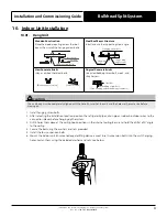
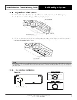
7.  Overhang the indoor unit onto the hanging screw bolts with block. If the drain pump is being used, position the 

indoor unit on a flat level by using the level indicator. If a gravity fed drain is being used, ensure there is adequate 
fall.

Roof beam

Hanging screw bolts

(Blade shape insertion)

(Slide insertion)

Hanging screw bolt

Hanging 
bolts

Supporting

 angle steel

Screw nut 

Washer Hanging 

screw bolt

Overhang part

Shockproof cushion

Page 21

Ceiling 

Steel bar

Embedding screw bolt

(Pipe hanging and embedding screw bolt) 

NOTE

Confirm the minimum drain tilt is 2.5% of the length 
and 2.5% of the width of the indoor unit.

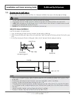
10.02.  Duct and Accessories Installation

1.   Install a filter according to air inlet size.
2.   Install the canvas tie-in between the body and duct.
3.   Air inlet and air outlet duct should be apart far enough to avoid air passage short-cycling.

Canvas tie-in  Canvas tie-in

Air outlet

Isolation booth

Isolation booth

checking orifice

Air inlet

Air dust filter

Air return flange

Ventilation panel

Ventilation panel

Ventilation panel

Air return flange 

Or

Air return flange

NOTE

The min. length of the duct should be more than 1m, and fixed on the air inlet by screws (applicable to the unit that the 
air inlet filter is not fasten by screws).

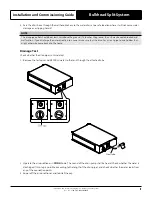
4.   Please refer to the following static pressure to install.

Model

Static Pressure (Pa)

BRE-026CS

0~40

BRE-035CS

0~40

BRE-050CS

0~60

BRE-070CS

0~100

Change the fan motor static pressure according to external duct static pressure.

NOTE

•  Do not place the connecting duct weight on the indoor unit.
•  When connecting the duct, use an nonflammable canvas tie-in to prevent vibrating.
•  Insulation foam must be wrapped outside the duct to avoid condensate. An internal duct under layer can be added to 

reduce noise, if the end-user requires.

Содержание BRE-026CS

Страница 1: ...e installing or operating your air conditioning unit Make sure to save this manual for future reference Model Numbers BRE 026CS BRE 035CS BRE 050CS BRE 070CS CAUTION The system is charged with flammab...

Страница 2: ...0 14 Test Run 21 MUST BE INSTALLED BY A LICENSED ELECTRICIAN DIY DIY DIY ALL ELECTRICAL WORK MUST BE PERFORMED BY A LICENSED ELECTRICIAN FOR COMPLIANCE WITH QUEENSLAND ELECTRICAL SAFETY REGULATIONS 20...

Страница 3: ...All electrical wiring must be in accordance with current electrical authority regulations and all wiring connections to be as per electrical diagram provided with the unit 03 General Information The A...

Страница 4: ...mance capacity that are among the best in the market the ActronAir air conditioning units provide the solution for the reduction of energy consumption CO2 emission high fuel dependency and high networ...

Страница 5: ...e room size corresponds to the room area as specific for operation without continuously operating open flames for example an operating gas appliance and ignition sources for example an operating elect...

Страница 6: ...quipment does not leak or contain moisture Take into consideration the correct amount of refrigerant charge specified for the system to ensure efficient unit operations When charging is complete recla...

Страница 7: ...ded with the air conditioner must be purchased separately Name Quantity Illustration Tubing Fittings Soundproof Insulation Sheath 2 Seal Sponge 1 Wired Controller Wired Controller 1 Wired Controller S...

Страница 8: ...te controller based on customer preferences and requirements and install in an appropriate place Refer to catalogues and technical literature for guidance on selecting a suitable remote controller 07...

Страница 9: ...locations In areas with oil drilling or fracking In areas with caustic gases in the air such as near hot spring In enclosed spaces such as cabinets In areas with strong electromagnetic waves In areas...

Страница 10: ...nt te ed d h ho oo ok k Air filter Electric control box Air filter Air Intake Condensate Drain 25mm OD Air Intake Air Intake Model Outline Dimensions Supply Air Return Air Mounting Width Height Total...

Страница 11: ...ng screw bolt Pipe hanging and embedding screw bolt Original Concrete Bricks Use an embedding screw bolt crock and stick harness Roof beam Hanging screw bolts Blade shape insertion Slide insertion Han...

Страница 12: ...uld be apart far enough to avoid air passage short cycling Canvas tie in Canvas tie in Air outlet Isolation booth Isolation booth checking orifice Air inlet Air dust filter Air return flange Ventilati...

Страница 13: ...ide using the following steps 1 Take off ventilation panel and flange cut off the staples at the side rail 2 Stick the attached seal sponge as per the indicating place see below and then change the mo...

Страница 14: ...nsure correct electrical tag out procedures are followed before commencing work Take rear ventilated as example Motor Maintainance 1 Remove the ventilated panel 2 Remove the blower housing 3 Remove th...

Страница 15: ...o the unit s outlet pipe Sheath the mouth of the hose and clip it firmly with a pipe clasp 3 Ensure the drain pipe has flex by installing clear tube or similar to prevent drain breakage or cracking Dr...

Страница 16: ...TE When connecting multiple drainpipes install the pipes as shown below 0 550mm 100mm 4 Using a 65 mm core drill drill a hole in the wall Make sure that the hole is drilled at a slight downward angle...

Страница 17: ...lfunction If you discharge the water directly into a sewer make sure that the drain has a U or S pipe to catch odour that might otherwise come back into the house Drainage Test Check whether the drain...

Страница 18: ...ed size to ensure minimal voltage drop at supply terminals No other equipment should be connected to the same sub circuit as the A C unit The unit s power information can be found on the rating sticke...

Страница 19: ...N L POWER SUPPLY See Outdoor Unit MRC Installation Guide for suggested minimum N INDOOR UNIT N L2 Field wiring by Installer 1mm 2 CORE EARTH S S 14 0 20 0 44mm SHIELDED DATA CABLE WITH SHIELD WIRE CON...

Страница 20: ...ALARM NO RELAY OUTPUT 24V AC DC 0 5A MAX BY INSTALLER WIRED CONTROLLER WC 02 4 CORE SHIELDED CABLE COMES WITH WC 02 CN34 CN10 CHOKE M INDOOR COIL TEMPERATURE SENSOR T2 BLACK ROOM TEMPERATURE SENSOR T1...

Страница 21: ...mperature is being registered correctly c Ensure the indicators on the wall control and the display panel on the indoor unit work properly d Check the airflow supplied matches the design conditions sp...

Страница 22: ...Installation and Commissioning Guide Bulkhead 2 Split System Doc No 9590 5011 Ver 1 211217 22 Notes Bulkhead Split System...

Страница 23: ...Installation and Commissioning Guide Bulkhead 2 Split System Doc No 9590 5011 Ver 1 211217 23 Notes Bulkhead Split System...

Страница 24: ...Engineering Pty Limited ActronAir is constantly seeking ways to improve the design of its products Therefore specifications are subject to change without notice Refrigerant Trading Authorisation No AU...

Отзывы: