background image

Technical description 

30 – EN 


ACT 600 – 5000


7.16 Electronic drainer 

This drain consists of a condensate accumulator where a capacitive sensor continuously checking liquid 
level is placed: as soon as the accumulator is filled, the sensor passes a signal to the electronic control and 
a diaphragm solenoid valve will open to discharge the condensate. For a complete condensate discharge 
the valve opening time will be adjusted exactly for each single drain operation. No condensate strainers are 
installed. No adjusting is required. A service valve is installed before the electronic drain in order to make 
check and maintenance easily.  

At dryer start-up verify that this valve is open.


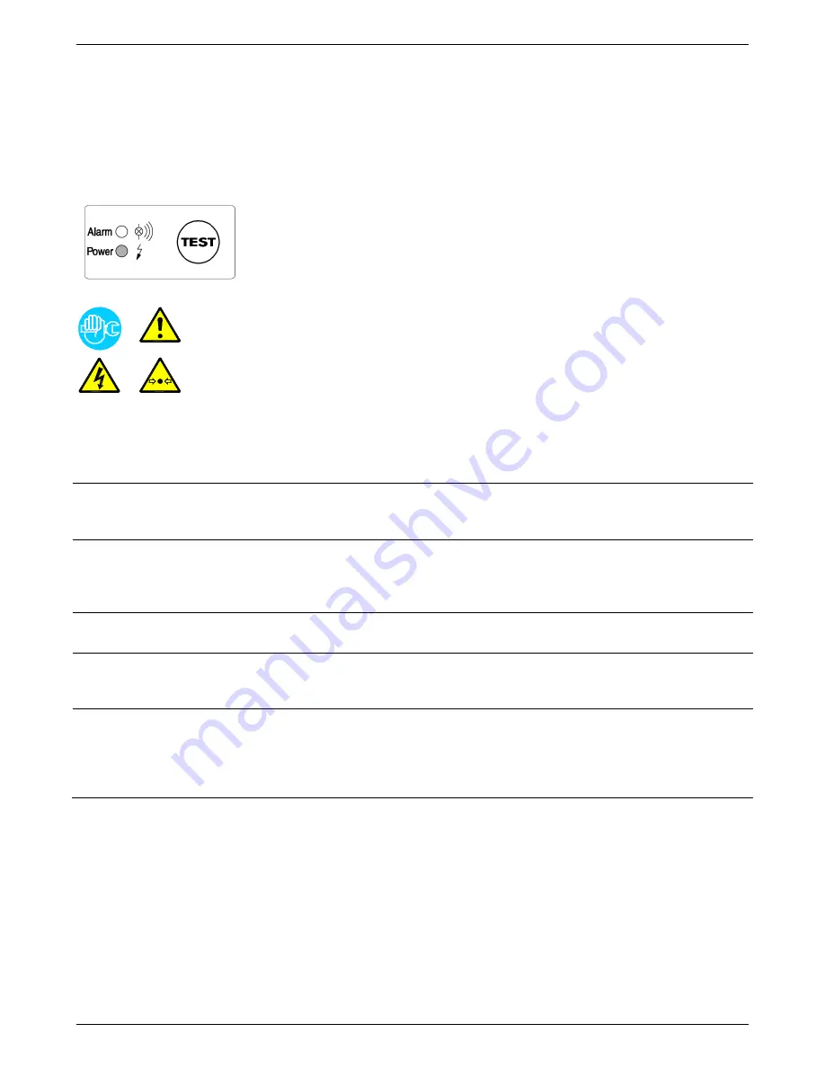
Control panel 


Power Led  On - drainer ready to work / supplied 

Alarm Led  Blinking - drainer in alarm condition 

TEST Button  Discharge test (keep pushed for 2 seconds) 

Troubleshooting 


Only qualified personnel should perform troubleshooting and or


maintenance 

operations. 
Prior to performing any maintenance or service, be sure that : 


no part of the machine is powered and that it cannot be connected to the mains 
supply. 


no part of the machine is under pressure and that it cannot be connected to the 
compressed air system. 


maintenance personnel have read and understand the safety and operation 
instructions in this manual. 


SYMPTOM 

POSSIBLE CAUSE - SUGGESTED ACTION 

 No led lighting up. 

 Verify that the system is powered. 

 Verify the electric wiring (internal and/or external). 

 Check internal printed circuit board for possible damage. 

 Pressing of Test button, but 

no condensate discharge. 

 The service valve located before the drain is closed - open it.


 The dryer is not under pressure - restore nominal condition.


 Solenoid valve defective - replace the drain. 


 The internal printed circuit board is damaged - replace the drain. 

 Condensate discharge only 

when Test button is pressed. 

 The capacitive sensor is too dirty - open the drain and clean the sensor 

plastic tube.  

 Drain keeps blowing off air. 

 The diaphragm valve is dirty - open the drain and clean it. 


 The capacitive sensor is too dirty - open the drain and clean the sensor 

plastic tube. 

 Drain in alarm condition. 

 The capacitive sensor is too dirty - open the drain and clean the sensor 

plastic tube.


 The service valve located before the drain is closed - open it.


 The dryer is not under pressure - restore nominal condition.


 Solenoid valve defective - replace the drain.  

NOTE : When the drain is in alarm condition, the diaphragm solenoid valve will open 7.5 sec every 4 
min. 


Содержание 1500-2500

Страница 1: ...Refrigerating air dryer ACT 600 5000 Air water cooled EN User s maintenance and spare parts manual 7425MUM178_EN_2012 10 CANADA ...

Страница 2: ...turing faults and to demonstrate that the device can perform all the functions for which it has been designed Once the dryer has been properly installed according to the instructions in this manual it will be ready for use without any further adjustment The operation is fully automatic and the maintenance is limited to few controls and some cleaning operations as detailed in the following chapters...

Страница 3: ... 19 7 3 Flow diagram Air Cooled 20 7 4 Flow diagram Water Cooled 20 7 5 Refrigerating compressor 21 7 6 Condenser Air Cooled 21 7 7 Condenser Water Cooled 21 7 8 Condenser water regulating valve Water Cooled 21 7 9 Filter dryer 21 7 10 Capillary tube 22 7 11 Alu Dry module 22 7 12 Hot gas by pass valve 22 7 13 Refrigerant pressure switches LPS HPS 23 7 14 Compressor crankcase heater 23 7 15 Electr...

Страница 4: ...ed 49 9 2 6 ACT 3000 3750 Water Cooled 50 9 2 7 ACT 4000 5000 Air Cooled 51 9 2 8 ACT 4000 5000 Water Cooled 52 9 3 Electric diagrams 53 9 3 1 ACT 600 1250 Sheet 1 of 3 53 9 3 2 ACT 600 1250 Sheet 2 of 3 54 9 3 3 ACT 600 1250 Sheet 3 of 3 55 9 3 4 ACT 1500 2500 Sheet 1 of 4 56 9 3 5 ACT 1500 2500 Sheet 2 of 4 57 9 3 6 ACT 1500 2500 Sheet 3 of 4 58 9 3 7 ACT 1500 2500 Sheet 4 of 4 59 9 3 8 ACT 3000...

Страница 5: ...l faulty parts which will be repaired or replaced free of charge except the travel hotel and restaurant expenses of our engineer The warranty doesn t cover any responsibility for direct or indirect damages to persons animals or equipment caused by improper usage or maintenance and it s limited to manufacturing faults only The right to warranty repairs is subordinated to the strict compliance with ...

Страница 6: ...removed Maintenance or control operation to be performed by qualified personnel only 1 ARIA AIR LUFT AIR Compressed air inlet connection point ARIA AIR LUFT AIR Compressed air outlet connection point Condensate drain connection point Cooling water inlet connection point Water Cooled Cooling water outlet connection point Water Cooled Operations which can be performed by the operator of the machine ...

Страница 7: ...ligence or misapplication Unauthorized alterations will immediately void the warranty In case of fire use an approved fire extinguisher water is not an acceptable means in cases of electrical fire 3 3 Proper use of the dryer This dryer has been designed manufactured and tested for the purpose of separating the humidity normally contained in compressed air Any other use has to be considered imprope...

Страница 8: ...piping TAMPERING MODIFICATION AND IMPROPER USE OF THE PRESSURE EQUIPMENT ARE FORBIDDEN Users of the equipment must comply with all local and national pressure equipment legislation in the country of installation 4 Installation 4 1 Transport Check for visible loss or damage if no visible damage is found place the unit near to the installation point and unpack the contents To move the packaged unit ...

Страница 9: ...ent conditions or extreme dust and dirt In case of fire use an approved fire extinguisher water is not an acceptable means in cases of fire Minimum installation requirements Select a clean dry area free from dust and protected from atmospheric disturbances The supporting area must be smooth horizontal and able to hold the weight of the dryer Minimum ambient temperature 34 F 1 C Maximum ambient tem...

Страница 10: ...ional installation of a pre filter 5 micron minimum to prevent a clogging of the heat exchanger Type A installation is suggested when the compressor operates at reduced intermittence and the total consumption equals the compressor flow rate Type B installation is suggested when the air consumption can consistently change with peak values highly exceeding the flow rate of the compressors The capaci...

Страница 11: ... pressure 120 psig 8 barg Ambient temperature 115 F 45 C Inlet air temperature 122 F 50 C Pressure DewPoint 50 F 10 C Factor F1 1 07 Factor F2 0 78 Factor F3 0 68 Factor F4 1 36 Each item of data has a corresponding numerical factor which multiplied by the design air flow is as follows Air flow capacity 600 x 1 07 x 0 78 x 0 68 x 1 36 463 scfm 787 m h 463 scfm 787 m h This is the maximum flow rate...

Страница 12: ...ersonnel only Never work on system under pressure The user is responsible to ensure that the dryer will never be operated with pressure exceeding the maximum pressure rating on the unit data tag Over pressurizing the dryer could be dangerous for both the operator and the unit The temperature and the amount of cooling water must comply with the limits indicated on the technical characteristics char...

Страница 13: ...th the consumption of the dryer while keeping into account also the ambient temperature the conditions of the mains installation the length of the cables and the requirements enforced by the local Power Provider CAUTION ATTENTION SHOULD BE PAID ON THE ROTATING DIRECTION OF THE COMPRESSOR The rotating direction of the compressor in this machine is cheched out by a Reverse Phase Protector RPP When t...

Страница 14: ...l the condensate drain coming from compressors dryers tanks filters etc 5 Start up 5 1 Preliminary operation Verify that the operating parameters match with the nominal values stated on the data nameplate of the dryer voltage frequency air pressure air temperature ambient temperature etc This dryer has been thoroughly tested packaged and inspected prior to shipment Nevertheless the unit could be d...

Страница 15: ... oil of the compressor Ensure the cooling water flow and temperature is adequate Water Cooled Press key for at least 2 seconds to start the dryer if the compressor has been shut down for enough time it will start up immediately otherwise the display will show the countdown of the seconds before the compressor starts up again and the led flashes max delay 5 minutes Ensure the consumption matches wi...

Страница 16: ...t is within range Shut down the air compressor After few minutes shut down the dryer keeping the button on DMC24 pressed for at least 2 seconds The display shows Dryer remote control ON OFF See instructions on paragraph 7 15 7 Use dry contacts only potential free suitable for low voltage Assure an adequate isolation of potentially dangerous powered parts CAUTION AUTO RESTART REMOTE ON OFF THE DRYE...

Страница 17: ...Technical data ACT 600 5000 17 EN 6 Technical data 6 1 Technical data ACT 600 5000 3 460 60 ...

Страница 18: ...Technical data 18 EN ACT 600 5000 6 2 Technical data ACT 600 5000 3 575 60 ...

Страница 19: ...e air then passes back through the air to air heat exchanger to be reheated to within 8 degrees of the incoming air temperature as it exits the dryer Refrigerant circuit Refrigerant gas is cycled through the compressor and exits at high pressure to a condenser where heat is removed causing the refrigerant to condense to a high pressure liquid state The liquid is forced through a capillary tube whe...

Страница 20: ...anger 12 4 T4 Temperature probe Compressor discharge 1c Condensate separator 13 Condensate drain service valve 2 Refrigerant pressure switch LPS 18 Condenser Water Cooled 4 Refrigerant pressure switch HPS 19 Condenser water regulating valve Water Cooled 6 Compressor 20 Refrigerant accumulator 7 Hot gas by pass valve ACT 3000 5000 A Cooled ACT 600 5000 W Cool 8 Condenser Air Cooled 21 Electronic dr...

Страница 21: ...r refrigerating gas exchanger where the cooling water lowers the temperature of the refrigerating gas The temperature of the inlet water must not exceed the nominal values It must also guarantee an adequate flow and that the water entering the exchanger is free from dust and other impurities 7 8 Condenser water regulating valve Water Cooled The condenser water regulating valve is used to keep the ...

Страница 22: ...he refrigerant preventing liquid return to the compressor The high efficiency condensate separator is located within the heat exchanger module No maintenance is required and the coalescing effect results in a high degree of moisture separation 7 12 Hot gas by pass valve This valve injects part of the hot gas taken from the discharge side of the compressor in the pipe between the evaporator and the...

Страница 23: ...ceeds the pre set value It features a manual resetting button mounted on the controller itself Calibrated pressure R 407 C Stop 435 psig 30 barg Manual reset P 334 psi P 23 bar 7 14 Compressor crankcase heater At low temperatures oil can more easily be mixed with the refrigerant gas So when the compressor starts oil can be drawn into the refrigeration circuit and liquid hammering could occur To pr...

Страница 24: ... menu Remote control enabled ESC Drain test ESC Temperature in C info set Setup menu on Temperature in F log reset Reset alarms and or service Pressure in barg Pressure in psig The DMC24 controls all the operations alarms and dryer operation set up The display and the leds show all the operating conditions Led shows that the compressor is ON The operation of the fans is indicated by the leds and D...

Страница 25: ... info menu is confirmed by message on the display first parameter of the menu Use the arrows and to move to the following previous Press info to show the value of the selected parameter Press info again to return to the list of displayable parameters Press ESC to exit info menu if no button is pressed after 2 minutes the menu is exited automatically Info Description T1 Temperature probe T1 DewPoin...

Страница 26: ...ed and the led flashes NOTE the operator maintenance technician must inspect the dryer and verify solve the problem that generated the service warning Service Warning Description PF1 Probe 1 Failure failure temperature probe 1 PF2 Probe 2 Failure failure temperature probe 2 PF3 Probe 3 Failure failure temperature probe 3 HdP High DewPoint DewPoint too high higher than the HdA value set LdP Low Dew...

Страница 27: ...after the alarms have been reset NOTE the operator maintenance technician must inspect the dryer and verify solve the problem that generated the service warning Alarm Description HP High Pressure the refrigerant high pressure safety pressure switch HPS tripped note the pressure switch has a reset button LP Low Pressure the refrigerant low pressure safety pressure switch LPS tripped COn Compressor ...

Страница 28: ...remote control the led turns on and it is no longer possible to switch the dryer ON or OFF from local panel the condensate drain test is possible and access to info and log menus Having contact between terminals 2 and 3 closed close the second contact between the terminals 1 and 2 to switch ON the dryer Open the contact between the terminals 1 and 2 to switch OFF the dryer Use dry contacts only po...

Страница 29: ... for condensate drain valve 1 20 min 1 min 1 HdA High DewPoint Alarm Alarm threshold for a high DewPoint the alarm disappears when the temperature drop 1 C 2 F below alarm point 0 0 25 0 C or 32 77 F 0 5 C or 1 F 20 or 68 Hdd High DewPoint Delay high DewPoint alarm enable delay 01 20 minutes 1 min 15 HdS High DewPoint alarm STOP select if high DewPoint alarm stops dryer YES or does not stop dryer ...

Страница 30: ... and that it cannot be connected to the compressed air system maintenance personnel have read and understand the safety and operation instructions in this manual SYMPTOM POSSIBLE CAUSE SUGGESTED ACTION No led lighting up Verify that the system is powered Verify the electric wiring internal and or external Check internal printed circuit board for possible damage Pressing of Test button but no conde...

Страница 31: ...ration of the condensate drain systems Verify the condenser for cleanliness Air Cooled Every 200 hours or monthly With an air jet max 2 bar 30 psig blowing from inside towards outside clean the condenser repeat this operation blowing in the opposite way be careful not to damage the aluminum fins of the cooling package Air Cooled Close the manual condensate drain valve unscrew the strainer if insta...

Страница 32: ...re start up DMC24 The led is lighted see specific point If the compressor still doesn t work replace it Condenser s fan doesn t work Air Cooled Verify the electric wiring Fan power contactor see KV1 KV2 on the electric diagram is faulty replace it DMC24 The led is lighted see specific point There is a leak in the refrigerant circuit contact a refrigeration engineer If the fan still doesn t work re...

Страница 33: ...rating correctly see paragraph 7 16 The dryer continuously drains condensate Electronic drainer is dirty see paragraph 7 16 Water within the line The dryer doesn t start see specific point If installed Untreated air flows through the by pass unit close the by pass The dryer doesn t drain the condensate see specific point DewPoint too high see specific point HPS high pressure switch has been activa...

Страница 34: ...efrigeration engineer Condensing pressure too high Check which of the following has caused the failure 1 The ambient temperature is too high or the room aeration is insufficient provide proper ventilation Air Cooled 2 The condenser unit is dirty clean it Air Cooled 3 The fan doesn t work see specific point Air Cooled 4 The temperature of the cooling water is too hot restore nominal conditions Wate...

Страница 35: ...IMMEDIATELY AND THE WARRANTY WILL BE VOIDED 4 Con one phase of power supply of dryer is missing see RPP on the electric diagram restore the missing phase 5 Con Reverse Phase Protector RPP is faulty replace it 6 Con electric protection of compressor tripped see Q1 QC1 on the electric diagram reset and verify the dryer s proper operation 7 Con if installed thermal protection inside the compressor tr...

Страница 36: ... T2 air IN verify electric wiring and or replace probe 3 PF3 temperature probe failure T3 compressor suction verify electric wiring and or replace probe 4 Hdp DewPoint too high higher than set HdA value see specific paragraph 5 Ldp DewPoint too low see specific paragraph 6 drn the condensate drainer does not work properly DRN contact open if electronic drainer is installed see specific paragraph 7...

Страница 37: ...se of abnormal operation so avoiding to wait for the spares delivery In case of failure of other parts for example inside the refrigerating circuit the replacement must be worked out by a refrigerating systems specialist or in our factory NOTE To order the suggested spare parts or any other part it s necessary to quote the data reported on the identification plate ...

Страница 38: ...Maintenance troubleshooting spare parts and dismantling 38 EN ACT 600 5000 ...

Страница 39: ...mical formula TLV GWP R407C HFC R32 125 134a 23 25 52 CHF2CF3 CH2F2 CH2FCF3 1000 ppm 1653 8 5 Dismantling of the dryer If the dryer is to be dismantled it has to be split into homogeneous groups of materials Part Material Refrigerant fluid R407C Oil Canopy and Supports Carbon steel Epoxy paint Refrigerating compressor Steel Copper Aluminium Oil Alu Dry Module Aluminium Condenser Unit Aluminium Cop...

Страница 40: ...ow diagram sticker 20 Refrigerant accumulator 83 Refrigerant service valve H P side 21 Electronic drainer 84 Refrigerant service valve L P side 22 Main switch 100 Autotransformer Electric diagrams List of components MC1 Compressor LPS Low pressure switch MV1 4 Condensers fans HPS High pressure switch DMC24 Electronic instr DMC24 Display module ELD Electronic drainer DMC24MA Electronic instr DMC24 ...

Страница 41: ...Attachments ACT 600 5000 41 EN 9 1 Dryers dimensions 9 1 1 ACT 600 1250 ...

Страница 42: ...Attachments 42 EN ACT 600 5000 9 1 2 ACT 1500 2500 ...

Страница 43: ...Attachments ACT 600 5000 43 EN 9 1 3 ACT 3000 3750 ...

Страница 44: ...Attachments 44 EN ACT 600 5000 9 1 4 ACT 4000 5000 ...

Страница 45: ...Attachments ACT 600 5000 45 EN 9 2 Exploded views 9 2 1 ACT 600 1250 Air Cooled ...

Страница 46: ...Attachments 46 EN ACT 600 5000 9 2 2 ACT 600 1250 Water Cooled ...

Страница 47: ...Attachments ACT 600 5000 47 EN 9 2 3 ACT 1500 2500 Air Cooled ...

Страница 48: ...Attachments 48 EN ACT 600 5000 9 2 4 ACT 1500 2500 Water Cooled ...

Страница 49: ...Attachments ACT 600 5000 49 EN 9 2 5 ACT 3000 3750 Air Cooled ...

Страница 50: ...Attachments 50 EN ACT 600 5000 9 2 6 ACT 3000 3750 Water Cooled ...

Страница 51: ...Attachments ACT 600 5000 51 EN 9 2 7 ACT 4000 5000 Air Cooled ...

Страница 52: ...Attachments 52 EN ACT 600 5000 9 2 8 ACT 4000 5000 Water Cooled ...

Страница 53: ... 3 460V 60Hz PE RCD Id 0 03A suggested Smin 2 5sqmm 14AWG Rev Note Sheet 01 of Drawing no 03 01 FU4 A TF FU1 2 FU3 B RC 2 7 3 MV1 TK M 2 1 KC1 11 12 TK W1 U1 V1 W2 U2 V2 2 2 2 6 4 KV1 1 3 5 See dryer nameplate OR 3 575V 60Hz PE 1 FRACT Q5478QCD001 L1 L2 L3 11 14 12 Technical modifications are subject to change without notice errors not excluded QS TR 1 With Auto Transformer TR installed ...

Страница 54: ... 6 5 1 5 4 3 A1 A2 KV2 2 0 KHP 24 21 14 1 4 14 11 RPP 13 Q1 1 3 MV1 2 0 KHP 14 11 25 27 26 DEWPOINT TEMP BT1 BT2 AIR IN TEMP BT3 BT4 24 22 23 P mA BHP 28 29 21 20 19 18 3 2 N 2 4 L 3 1 2 3 A 2 6 2 8 1 9 17 8 7 3 2 16 2 6 2 8 DMC24RU 1 3 1 6 1 5 1 3 1 6 1 5 A 13 10 3 1 L 2 3 3 2 N 2 4 ZL T Power ON Power OFF MAX 2A 48V and NO Alarm or Alarm 6 5 4 6 5 4 1 J1 DISPLAY EXP J2 J3 RS485 A B ELD FRACT Q54...

Страница 55: ...RE SWITCH HPS MV1 LPS 9 024 024 CDI 12 CDI DI2 DI4 2 1 5 4 3 6 UKK 5 13 11 10 12 14 RC1 00 10 RC2 00 DR1 DR2 CDI DI5 LOW PRESSURE SWITCH 8 7 00 UDT ELD AIR COOLED ONLY JUMP IF NOT INSTALLED ELECTRONIC LEVEL DRAINER FAN THERMAL PROTECTION FRACT Q5478QCD001 PE L1 L3 L2 Technical modifications are subject to change without notice errors not excluded S R L1 CBC 4 T L2 L3 FROM TR TANSFORMER 460V SIDE ...

Страница 56: ... KC1 1 3 QC1 2 7 QV1 See dryer nameplate TF FRACT Q5478QCD002 L1 L3 L2 RPP 11 14 2 6 12 W2 U1 V1 W1 U2 V2 2 3 KV2 KV1 2 2 KV0 2 1 U1 V1 W1 M 3 2 7 TK TK MV1 M 2 8 TK TK 3 MV2 Technical modifications are subject to change without notice errors not excluded W2 U2 V2 TR OR 3 575V 60Hz PE 1 Smin 6sqmm 10AWG RCD Id 0 03A suggested FUSE MAX 32 A 3 460V 60Hz PE 1 With Auto Transformer TR installed QS ...

Страница 57: ...2 13 14 QV1 1 5 N U N U 11 12 1 9 1 3 5 3 1 6 4 2 1 6 1 7 1 3 1 3 1 7 1 6 DMC24MA 27 K 15 13 9 14 29 28 T II I 11 12 10 22 26 25 24 23 21 20 ZL 8 7 19 18 B J3 RS485 DISPLAY 1 2 3 4 5 6 A 17 16 EXP J2 J1 5 NO Alarm and MAX 2A 48V Power ON 4 Power OFF 4 6 Alarm or 5 6 A A1 KHP 2 0 24 21 A1 A1 KC1 KV2 KV1 A2 A2 A2 DEWPOINT TEMP AIR IN TEMP 00 3 2 3 0 MV1 FRACT Q5478QCD002 KV0 A1 A2 N U 12 11 3 5 1 4 ...

Страница 58: ...f 4 0 1 3 2 4 5 6 7 8 9 Rev Note Sheet 03 of Drawing no 04 01 B A 11 14 22 24 2 8 KDR 2 5 KDR 2 5 3 2 1 3 2 4 1 2 3 1 2 3 1 1 3 2 1 3 2 4 N 3 1 2 3 L 2 8 ELD1 ELD2 FRACT Q5478QCD002 Technical modifications are subject to change without notice errors not excluded ...

Страница 59: ...24 17 32 CDI 16 15 33 00 20 18 19 9 1 5 3 2 4 7 6 8 10 11 12 13 14 MV2 21 22 DI5 34 ELD1 ELD2 FRACT Q5478QCD002 AIR COOLED ONLY JUMP IF NOT INSTALLED FAN THERMAL PROTECTION AIR COOLED ONLY JUMP IF NOT INSTALLED FAN THERMAL PROTECTION ELECTRONIC LEVEL DRAINER ELECTRONIC LEVEL DRAINER L3 L1 L2 PE Technical modifications are subject to change without notice errors not excluded S R T L2 L1 CBC 4 L3 FR...

Страница 60: ...FU3 B RC 3 2 KC1 11 12 3 6 5 6 3 2 MC1 3 U T1 V T2 M W T3 2 4 KC1 1 3 QC1 See dryer nameplate TF FRACT UQ5478QCD003 L1 L3 L2 RPP 11 14 3 6 12 3 6 TK TK 2 0 L L2 L3 L1 N S1 S2 M2 M1 M 3 3 6 V T2 W T3 U T1 TR QS FUSE MAX 63 A RCD Id 0 03A suggested Smin 16sqmm 6AWG 3 575V 60Hz PE 1 3 460V 60Hz PE 1 With Auto Transformer TR installed OR ...

Страница 61: ...of 6 0 1 3 2 4 5 6 7 8 9 Rev Note Sheet 02 of Drawing no 06 00 3 7 QV1 FRACT UQ5478QCD003 3 3 KV2 KV1 3 2 KV0 3 1 MV2 MV1 3 7 3 7 M V1 3 U1 TK W1 TK M U1 V1 TK 3 W1 W2 TK U2 V2 3 8 MV4 3 V1 M 3 8 TK U1 TK W1 MV3 M U1 TK V1 3 TK W1 1 9 W2 U2 V2 W2 U2 V2 U2 W2 V2 ...

Страница 62: ...QV1 1 5 N U N U 11 12 1 9 1 3 5 3 1 6 4 2 2 2 2 3 1 3 1 3 2 3 2 2 DMC24MA 27 K 15 13 9 14 29 28 T II I 11 12 10 22 26 25 24 23 21 20 ZL 8 7 19 18 B J3 RS485 DISPLAY 1 2 3 4 5 6 A 17 EXP J2 J1 5 NO Alarm and MAX 2A 48V Power ON 4 Power OFF 4 6 Alarm or 5 6 A A1 KHP 2 0 24 21 A1 A1 KC1 KV2 KV1 A2 A2 A2 DEWPOINT TEMP CONDENSING PRESS COMPRES DISCHARGE TEMP COMPRES SUCTION TEMP AIR IN TEMP 00 4 2 4 0 ...

Страница 63: ...6 0 1 3 2 4 5 6 7 8 9 Rev Note Sheet 04 of Drawing no 06 00 B A 5 9 6 10 3 8 KDR 3 5 KDR 3 5 3 2 1 3 2 4 1 2 3 1 2 3 1 1 3 2 1 3 2 4 N 3 1 2 3 L ELD1 ELD2 FRACT UQ5478QCD003 8 7 ELD3 1 3 3 2 N 2 4 3 1 L 2 3 ELD4 3 2 1 3 1 2 2 4 3 1 1 1 2 3 11 3 5 KDR 12 3 8 KDR 3 5 ...

Страница 64: ...3 T3 S4 R4 T4 T4 S4 R4 MC1 6 5 DI3 15 HIGH PRESSURE SWITCH LOW PRESSURE SWITCH COMPRESSOR THERMAL PROTECTION AIR COOLED ONLY JUMP IF NOT INSTALLED FAN THERMAL PROTECTION AIR COOLED ONLY JUMP IF NOT INSTALLED FAN THERMAL PROTECTION AIR COOLED ONLY JUMP IF NOT INSTALLED FAN THERMAL PROTECTION AIR COOLED ONLY JUMP IF NOT INSTALLED FAN THERMAL PROTECTION ONLY ACT 5000 JUMP IF NOT INSTALLED COMPRESSOR ...

Страница 65: ...Attachments ACT 600 5000 65 EN 9 3 13 ACT 3000 5000 Sheet 6 of 6 0 1 3 2 4 5 6 7 8 9 Rev Note Sheet 06 of Drawing no 06 00 FRACT UQ5478QCD003 ...

Страница 66: ...Blank pages 66 EN ACT 600 5000 10 Blank pages ...

Страница 67: ...Blank pages ACT 600 5000 67 EN ...

Страница 68: ...Original instructions are in ENGLISH Subject to technical changes without prior notice errors not excluded ...

Отзывы: