Technical description
22 – EN
ACT 600 – 5000
7.10 Capillary tube
It consists of a piece of reduced cross section copper tubing located between the condenser and the
evaporator, acting as a metering device to reduce the pressure of the refrigerant. Reduction of pressure is a
design function to achieve optimum temperature reached within the evaporator: the smaller the capillary
tube outlet pressure, the lower the evaporation temperature.
The length and interior diameter of the capillary tubing is accurately sized to establish the performance of
the dryer; no maintenance or adjustment is necessary.
7.11 Alu-Dry module
The heat exchanger module houses the air-to-air, the air-to-refrigerant heat exchangers and the demister
type condensate separator. The counter flow of compressed air in the air-to-air heat exchanger ensures
maximum heat transfer. The generous cross section of flow channel within the heat exchanger module leads
to low velocities and reduced power requirements. The generous dimensions of the air-to-refrigerant heat
exchanger plus the counter flow gas flow allows full and complete evaporation of the refrigerant (preventing
liquid return to the compressor). The high efficiency condensate separator is located within the heat
exchanger module. No maintenance is required and the coalescing effect results in a high degree of
moisture separation.
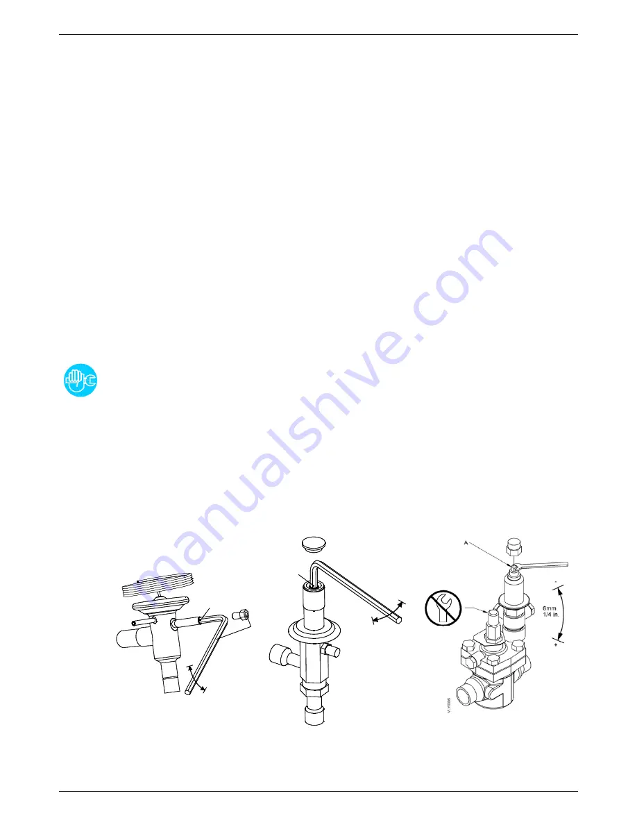
7.12 Hot gas by-pass valve
This valve injects part of the hot gas (taken from the discharge side of the compressor) in the pipe between
the evaporator and the suction side of the compressor, keeping the evaporation temperature/pressure
constant at approx. +36°F (+2°C). This injection prevents the formation of ice inside the dryer evaporator at
every load condition.
ADJUSTMENT
The hot gas by-pass valve is adjusted during the manufacturing testing phase. As a rule no
adjustment is required; anyway if it is necessary the operation must be carried out by an
experienced refrigerating engineer.
WARNING
the use of ¼” Schrader service valves must be justified by a real malfunction of the refrigerating
system. Each time a pressure gauge is connected, a part of refrigerant is exhausted.
Without compressed air flow through the dryer, rotate the adjusting screw (position A on the
drawing) until the following value is reached:
Hot gas setting :
R407C pressure 65.3 psig (+1.45 / -0 psi) [4.5 barg (+0.1 / -0 bar)]
ACT 600 – 1250
2 x
A
4 mm
5/32 in.
+
-
V
LY
00
0
1
ACT 1500 – 3000
A
8 mm
5/16 in.
-
+
V
L
Y
00
0
3
ACT 3750 – 5000
Содержание 1500-2500
Страница 17: ...Technical data ACT 600 5000 17 EN 6 Technical data 6 1 Technical data ACT 600 5000 3 460 60 ...
Страница 18: ...Technical data 18 EN ACT 600 5000 6 2 Technical data ACT 600 5000 3 575 60 ...
Страница 38: ...Maintenance troubleshooting spare parts and dismantling 38 EN ACT 600 5000 ...
Страница 41: ...Attachments ACT 600 5000 41 EN 9 1 Dryers dimensions 9 1 1 ACT 600 1250 ...
Страница 42: ...Attachments 42 EN ACT 600 5000 9 1 2 ACT 1500 2500 ...
Страница 43: ...Attachments ACT 600 5000 43 EN 9 1 3 ACT 3000 3750 ...
Страница 44: ...Attachments 44 EN ACT 600 5000 9 1 4 ACT 4000 5000 ...
Страница 45: ...Attachments ACT 600 5000 45 EN 9 2 Exploded views 9 2 1 ACT 600 1250 Air Cooled ...
Страница 46: ...Attachments 46 EN ACT 600 5000 9 2 2 ACT 600 1250 Water Cooled ...
Страница 47: ...Attachments ACT 600 5000 47 EN 9 2 3 ACT 1500 2500 Air Cooled ...
Страница 48: ...Attachments 48 EN ACT 600 5000 9 2 4 ACT 1500 2500 Water Cooled ...
Страница 49: ...Attachments ACT 600 5000 49 EN 9 2 5 ACT 3000 3750 Air Cooled ...
Страница 50: ...Attachments 50 EN ACT 600 5000 9 2 6 ACT 3000 3750 Water Cooled ...
Страница 51: ...Attachments ACT 600 5000 51 EN 9 2 7 ACT 4000 5000 Air Cooled ...
Страница 52: ...Attachments 52 EN ACT 600 5000 9 2 8 ACT 4000 5000 Water Cooled ...
Страница 66: ...Blank pages 66 EN ACT 600 5000 10 Blank pages ...
Страница 67: ...Blank pages ACT 600 5000 67 EN ...
Страница 68: ...Original instructions are in ENGLISH Subject to technical changes without prior notice errors not excluded ...


