ACR38 Reference Manual
version 1.9 February 2006
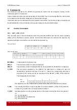
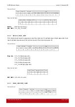
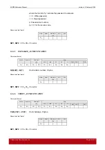
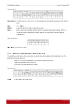
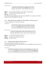
Response data format
Header
Status
Data length
BYTE 1
…
…
BYTE N
SW1
SW2
LEN
01
H
BYTE x
Data read from memory card
SW1, SW2
= 90
H
00
H
if no error
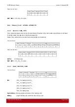
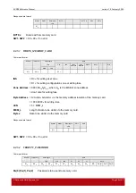
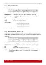
8.2.5.3 WRITE_MEMORY_CARD
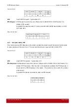
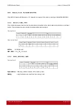
Command format
Header
Instruction
Data length
Data
LEN
CLA
INS
Zone
Address
Byte
Address
MEM_L
Byte 1
....
.... Byte n
MSB
LSB
01
H
A0
H
FF
H
INS
=
D0
H
for writing user zone
=
D1
H
for writing configuration zone or writing fuse
Zone Address
= 0000 0A
10
A
9
A
8
b
, where A
10
is the MSB of zone address
= don’t care for writing fuse
Byte Address
= A
7
A
6
A
5
A
4
A
3
A
2
A
1
A
0
b
is the memory address location of the memory card.
= 1000 0000
b
for writing fuse
LEN
= 5 + MEM_L
MEM_L
Length of data to be written to the memory card.
Byte x
Data to be written to the memory card.
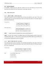
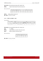
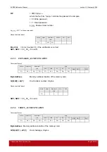
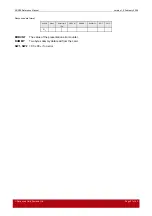
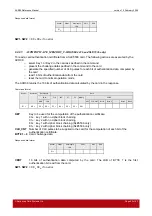
Response data format
Header
Status
Data length
SW1
SW2
LEN
01
H
SW1, SW2
= 90
H
00
H
if no error
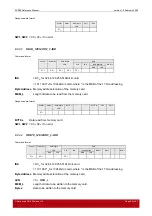
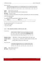
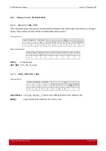
8.2.5.4 VERIFTY_PASSWORD
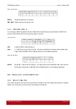
Command format
Header
Instruction
Data length
Data
LEN
CLA
INS
P1
P2
Lc
Data
01
H
A0
H
00
H
09
H
FF
H
20
H
00
H
00
H
04
H
RP
Pw(0)
Pw(1)
Pw(2)
Pw(0),Pw(1),Pw(2)
Passwords to be sent to memory card.
Advanced Card Systems Ltd.
Page 25 of 43

