Chapter 3. Installing the Appliance
3
4
5
1
2
BMC
IPMI
1/10 GbE
10 GbE SFP+
VGA
USB
VGA
USB
VGA
USB
VGA
USB
VGA
USB
1 2
3 4
IPMI
1/10 GbE
10 GbE SFP+
1 2
3 4
IPMI
1/10 GbE
10 GbE SFP+
1 2
3 4
IPMI
1/10 GbE
10 GbE SFP+
1 2
3 4
IPMI
1/10 GbE
10 GbE SFP+
1 2
3 4
1
3
2
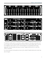
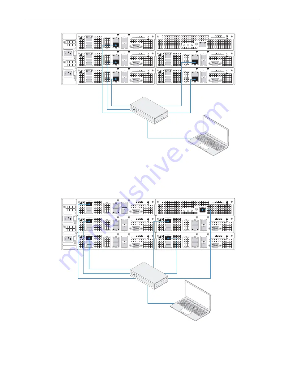
3. (Optional) Connect the out-of-band management network interfaces of each node and the chassis (
1
on
the diagram) to a switch with access to the IPMI subnet for your appliance (
2
on the diagram). The nodes
have preconfigured IPMI IP addresses: 10.20.30.11 to 10.20.30.15. The chassis has the preconfigured
IPMI IP address 10.20.30.10. Connect the admin laptop (
3
on the diagram) to the same switch.
3
4
5
1
2
BMC
IPMI
1/10 GbE
10 GbE SFP+
VGA
USB
VGA
USB
VGA
USB
VGA
USB
VGA
USB
1 2
3 4
IPMI
1/10 GbE
10 GbE SFP+
1 2
3 4
IPMI
1/10 GbE
10 GbE SFP+
1 2
3 4
IPMI
1/10 GbE
10 GbE SFP+
1 2
3 4
IPMI
1/10 GbE
10 GbE SFP+
1 2
3 4
1
2
3
9


