SERIES IP220 INDUSTRIAL I/O PACK
1
2
-BIT HIGH-DENSITY ANALOG OUTPUT MODULE
3. Read the PROM to retrieve the channel's unique gain calibration
error data. For channel 0, read byte CD BASE + 43H. An 8 bit
two's compliment number is read (assume Fl H). This
corresponds to a PROM_Gain_Error of -15 decimal.
4. Calculate the Ideal_Count required to provide an uncorrected
output of the desired value (-2.5 Volts) by using equation (2).
Ideal_Count
= [(4096 / 20) * -2.5] + 2048 = 1536.0
5. Calculate the Corrected_Count required to provide an accurate
output of the desired value (-2.5 Volts) by using equation (4).
Corrected_Count
= [(1 + (-15 / 16384)) * (1536.0 - 2048)] +
(2048 + (32 / 4)) = 1544.47
6. Write to the DAC Channel 0 Register © BASE + OOH with the
desired data (6080H - data is determined by rounding 1544.47
decimal to 1544, then converting to Hex 608 and left justifying
as 6080H).
7. (OPTIONAL) Observe or monitor that the specific DAC channel
(0) reflects the results of the digital data converted to an analog
output voltage at the field connector.
8. Repeat steps 2-7 to adjust the unique calibration characteristic
and update each channel used, or repeat steps 4-7 to update
the value of a single channel.
Error checking should be performed on the calculated count
values to insure that calculated values below 0 or above 4095
decimal are restricted to those end points. Note that the software
calibration cannot generate outputs near the endpoints of the range
which are clipped off due to the uncalibrated hardware (i.e. the
DAC).
4.0 THEORY OF OPERATION
This section describes the basic functionality of the IP220
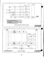
circuitry. Review the block diagram shown in Drawing 4501-439 as
you study the following paragraphs.
ANALOG OUTPUTS
The field I/O interface to the carrier board is provided through
connector P2 (refer to Table 2.3). Field analog outputs are
NON
-
ISOLATED. This means that the field return, output channel minus,
and logic common have a direct electrical connection to each other.
As such, care must be taken to avoid ground loops and excessive
output loading (see Section 2 for connection recommendations).
Ignoring this effect may cause operation errors, and with extreme
abuse, possible circuit damage. Refer to Drawing 4501-440 for
example analog output and grounding connections.
The fully populated board contains sixteen 12-bit DAC's (IP220-
16), one per channel. This allows each channel to be independently
programmed for maximum speed and accuracy and avoids the
problems associated with designs using sample and hold amplifiers
multiplexed to a single DAC. Each DAC may source up to 5mA of
output current without requiring separate buffer amplifiers. DAC
calibration is done via software to avoid the mechanical drawbacks
of hardware potentiometers for each DAC channel. This also
conserves board space and helps to achieve high channel density.
Calibration parameters are stored in PROM on a per channel basis.
DAC inputs are double-buffered. This allows channels to be
programmed by either of two modes (software register selectable).
The Transparent Mode allows channels to be updated quickly on an
individual basis, since data written to the input latch is immediately
transfered to the output latch and converted to an updated analog
output voltage. Selection of the Simultaneous Mode allows many or
all channels to be updated at once. In this mode, the data for
channels is written to their associated input latch, but does not get
transfered to the output latch until a Simultaneous Trigger command
is sent. All channels update synchronously and simultaneously
upon receipt of the trigger command.
The logic interface provides ±12 Volt supplies to the analog
circuitry. If desired, the user has the option of providing ±15 Volt
external supplies. However, supplies cannot be mixed (do not use
+12V with -15V). Rated outputs are achieved using either internal or
external supplies and this is selected via hardware jumpers J1 & J2
prior to powering the unit (see Section 2).
LOGIC/POWER INTERFACE
The logic interface to the carrier board is made through
connector P1 (refer to Table 2.4). Not all of the IP logic P1 pin
functions are used. P1 also provides ±12V and +5V to power the
module.
A programmable logic device installed on the IP Module
provides the control signals required to operate the board. It
decodes the selected addresses in the I/O and ID spaces, and
produces the chip selects, control signals, and timing required by
the DAC's, software registers, and ID
PROM,
as well as, the
acknowledgement signal required by the carrier board per the IP
specification. It also controls the mode selection and triggering to
start DAC conversions for the Transparent and Simultaneous
Modes.
The ID
PROM
(read only) installed on the IP module provides
the identification for the individual module per the IP specification.
The Calibration
PROM
(same physical device as the ID
PROM,
but
mapped into the I/O space) contains channel specific calibration
coefficients to correct both offset and gain errors. The coefficients
must be used to trim the outputs to within their accuracy
specification. The PROM, software registers, and DAC's are all
accessed through the 16-bit data bus interface to the carrier board.
5.0 SERVICE AND REPAIR
SERVICE AND REPAIR ASSISTANCE
Surface-Mounted Technology (SMT) boards are generally
difficult to repair. It is highly recommended that a non-functioning
board be returned to Acromag for repair. The board can be
damaged unless special SMT repair and service tools are used.
Further, Acromag has automated test equipment that thoroughly
checks the performance of each board. When a board is first
produced and when any repair is made, it is tested, placed in a bum-
in room at elevated temperature, and
retested
before shipment.
Please refer to Acromag's Service Policy Bulletin or contact
Acromag for complete details on how to obtain parts and repair.
PRELIMINARY SERVICE PROCEDURE
Before beginning repair, be sure that all of the procedures in
Section 2, Preparation For Use, have been followed. Also, refer to
the documentation of your carrier board to verify that it is correctly
configured. Replacement of the module with one that is known to
work correctly is a good technique to isolate a faulty module.
- 1 0 -


