SERIES AP440 ACROPACK
USER
’S MANUAL
Acromag, Inc. Tel: 248-295-0310
- 35 - http://www.acromag.com
- 35 -
www.acromag.com
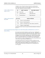
signal lines will cause an interrupt to be generated.
1. After power-up or reset, the module is always placed in the Standard
Operating Mode. To switch to the Enhanced Mode, execute four
consecutive write cycles to port 7 with the following data: 07H first, followed
by 0DH, followed by 06H, then 12H.
At this point, you are in Enhanced Mode bank 0. Port 7 would now be used
to access register banks 1 & 2.
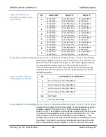
2. Write 80H to the port 7 address to select register bank 2 where
debounce will be configured for our port 0 input channels.
At this point, you are in Enhanced Mode Bank 2 where access to the
debounce configuration registers is obtained.
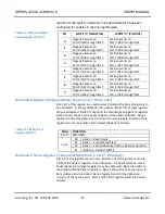
3. The default debounce duration is 3-4us using the 31.25MHz clock. This
time applies to the FPGA input signal and does not include opto-coupler
delay. Write 01H to the port 1 address of this bank to select a 64us
debounce time (Debounce Duration Register 0). An incoming signal must be
stable for the entire debounce time before it will be recognized as a valid
input transition by the FPGA.
4. Enable the debounce circuitry for port 0 inputs by setting bit 0 of the
Debounce Control Register. Write 01H to the Port 0 address of this bank
(Debounce Control Register).
If the module had been configured earlier, you would first read this register
to check the existing settings of debounce enable for the other ports of this
module with the intent of preserving their configuration by adjusting the
value written above.
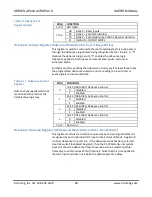
5. Write 40H to the port 7 address to select register bank 1 where the event
polarity requirements of our application will be configured.
At this point, you are in Enhanced Mode Bank 1 where access to the event
polarity/status registers is obtained.
6. For change-of-state detection, both positive and negative polarities must
be sensed. As such, two channels are required to detect a change-of-state
on a single input signal. For our example, IN00-IN03 will be used to detect
positive events (low-to-high transitions); IN04-IN07 will be used to detect
negative events (high-to-low transitions). Write 02H to the port 6 address to
set IN00-IN03 to positive edge detection, and IN04-IN07 to negative edge
detection.
Note that this port address has a dual function depending on whether a read
or write is being executed. As such, if the current polarity configuration for
the other ports must be preserved, then it must be remembered since it
cannot be read back.
7. To enable event sensing for the port 0 input points, write FFH to the

