12
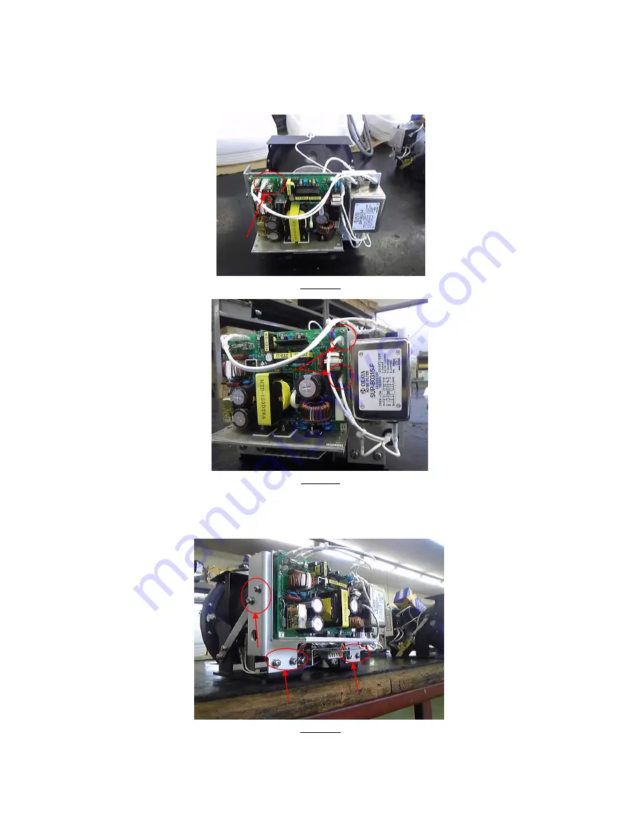
4) Remove the 4 cables as indicated in picture
10
and
11
.
Picture
5) Loosen and remove all screws (6) as indicated in picture
12.
Remove the complete ballast assembly with fitting plate
Страница 1: ...1 TROUBLE SHOOTING AND PARTS REPLACEMENT MANUAL FOR THE REMOTE CONTROLLED XENON SEARCH LIGHT RCL 600 ...
Страница 2: ...of PCB PP 207A Page 10 4 to replace the Ballast Page 11 5 to replace the Starter Page 14 6 to replace the Brush holder Page 16 7 to check the output Elevation of PCB PP 207A Page 19 8 to check the output Rotation of PCB PP 207A Page 20 9 to replace the PCB PP 207A Page 21 10 to replace the Elevation motor Page 23 11 to replace the PCB PP 208A Page 25 12 to check the Rotation gear Page 27 13 to rep...
Страница 3: ...according to directions on pages 8 and 9 How to check the ballast The Starter is faulty Replace the starter according to directions on pages 14 and 15 The Ballast is faulty Replace the ballast according to directions on pages 11 12 and 13 There is a possibility of a problem inside the driver PCB Replace the printed circuit board PP 207A according to directions on page 10 How to check the print cir...
Страница 4: ...le whether 9V DC is present see picture 3 page 8 YES NO The Elevation motor is faulty Replace the elevation motor according to the directions on pages 24 and 25 Check the print circuit board PP 207A according to the directions on page 20 YES NO Replace the brush holder according Replace the printed circuit board PP 207A to the directions on pages 17 18 according to the directions on pages 22 and 1...
Страница 5: ...page 28 29 and 30 Check for corrosion in the bearings or mechanical obstruction Check and repair Check the printed circuit board PP 207A according to the directions on pages 22 and 23 NO There is a possibility that the rotation motor or remote control panel is out of order Replace the rotation motor according to the instruction on pages 31 32 and 33 If there is no improvement replace the printed c...
Страница 6: ...n pages 37 38 YES There is a possibility of corrosion in the lamp holder and focus NO driving rack and this will prevent smooth functioning Repair the relevant part or send the unit in to ACR for repair The focus motor is faulty Replace the focus motor according to the instruction on pages 39 and 40 ...
Страница 7: ...ips screw driver 6 mm Hexagonal wrench 1 2 Working procedures 1 Loosen 4 screws as marked in picture 1 and carefully remove the front frame assembly Picture 1 2 Loosen and remove 2 screws as indicated in picture 2 Power head Picture 2 3 Carefully pull out the complete power head ...
Страница 8: ...e instruction on page 7 How to remove the power head 2 Loosen and remove 2 screws as indicated in picture 3 and remove the card edge receptacle from inside the search light See picture 3 Picture 3 3 Remove 2 cable plugs on the ballast as indicated in picture 4 4 Take the card edge receptacle and plug into the Ballast P C B assembly Refer picture 4 Picture 4 Plug in P C B 24V 9V ...
Страница 9: ...9 5 Turn on the power source by pushing the power button on the remote control panel Measure on the terminals indicated in picture 5 whether 170 DCV are available Picture 5 Terminal Terminal ...
Страница 10: ...upside down 2 Loosen and remove 8 screws as indicated in picture 6 Carefully lift the bottom cover off the base Picture 6 3 Remove 2 cable connectors P and N as indicated inside circle in picture 7 Picture 7 4 Turn on the power source by pushing the power button on remote control panel Measure on terminals P and N with the DC Multimeter for 24V output Refer to picture 7 ...
Страница 11: ...llast PXE 150 DC24 4 2 Procedure for exchanging the PCBs 1 Remove the power head according to the instruction on page 7 2 Remove the spring with pliers as indicated by the arrow in picture 8 Picture 8 3 Remove cables connected to the starter See picture 9 Note Remove cables after marking them in order to replace them in their proper order Picture 9 ...
Страница 12: ...4 Remove the 4 cables as indicated in picture 10 and 11 Picture 10 Picture 11 5 Loosen and remove all screws 6 as indicated in picture 12 Remove the complete ballast assembly with fitting plate Picture 12 ...
Страница 13: ...emove the ballast PCB from fitting plate by sliding it sideways to break the silicon heating compound seal Install the new PCB Note Install the ballast after applying a suitable amount of silicon heating compound between the ballast and fitting plate Note Picture 13 ...
Страница 14: ...ter unit STX 10 5 2 Replacement procedure 1 Remove the power head according to the instruction of page 7 2 Remove the spring by pliers where is the arrow mark on picture 14 Picture 14 3 Remove cables connected to the starter as shown in picture 15 Note Remove cables after marking them in order to replace them in their proper order Picture 15 ...
Страница 15: ...ve all the screws 6 as marked in picture 16 Remove the fitting plate complete with Ballast assembly Picture 16 5 Loosen and remove 4 screws as indicated in picture 17 remove and replace the starter Picture 17 Fitting plate ...
Страница 16: ...Brush holder assembly B3A00140 6 2 Procedures for change 1 Remove the search light and place upside down on a suitable surface 2 Loosen and remove 8 screws as shown in picture 18 Carefully lift the bottom cover off the base Picture 18 3 Remove all the cables connected to the PCB in order to place the bottom cover to one side See picture 19 Picture 19 ...
Страница 17: ... screws as indicated in picture 20 Carefully remove the printed circuit board PP207 Picture 20 5 Loosen and remove 3 screws as indicated in picture 21 Carefully pull out the brush holder complete with mounting plate Picture 21 ...
Страница 18: ...18 6 Loosen and remove 4 screws as indicated in picture 22 Replace the complete brush holder assembly Picture 22 Carefully reverse the process to re assemble the light ...
Страница 19: ...r 7 2 Procedure 1 Remove the search light and place upside down on a suitable surface 2 Loosen and remove 8 screws as indicated in picture 23 Carefully lift the bottom cover off the base Picture 23 3 Turn on the power source on the remote control panel and move the joy stick in elevation Measure 8V between terminals 3 and 4 of CN2 as indicated in picture 24 Picture 24 ...
Страница 20: ...re 1 Remove the search light and place upside down on a suitable surface 2 Loosen and remove 8 screws as indicated in picture 25 Carefully lift the bottom cover off the base Picture 25 8 3 Turn on the power source on remote control panel and move the joy stick to the right or left Measure approx 8V between terminals 1 and 2 of CN3 where is the arrow mark on picture 26 Picture 26 ...
Страница 21: ...it board PP 207A 9 2 Procedure 1 Remove the search light and place upside down on a suitable surface 2 Loosen and remove 8 screws as indicated in picture 27 Carefully lift the bottom cover off the base Picture 27 3 Remove all the cables where connected to the print circuit board Remove the bottom cover See picture 28 Picture 28 ...
Страница 22: ...22 1 Loosen and remove 4 screws as indicated in picture 29 Replace PCB Picture 29 ...
Страница 23: ...at screw driver 7mm Spanner Pliers Elevation motor TE 24SM 12 256S 10 2Procedures to check motor 1 Remove the power head according to the instruction of page 7 How to remove the power head 2 Remove the spring with pliers where indicated in picture 30 Picture 30 3 Remove center connector as indicated in picture 31 Picture 31 ...
Страница 24: ...screws as indicated in picture 32 Picture 32 5 Loosen and remove 2 screws as indicated in picture 33 and remove the elevation motor Picture 33 6 Loosen and remove 4 screws as indicated in picture 34 and replace motor Picture 34 ...
Страница 25: ...llips head screw driver 7mm Spanner Printed circuit board PP 208A 11 2 Replacement procedure 1 Loosen and remove 4 screws as indicated in picture 35 Open the cover Picture 35 Remote control panel CPF99 2 Remove all the connectors from the printed circuit board as indicated in picture 36 Picture 36 ...
Страница 26: ...26 3 Loosen and remove 4 screws 4 places as indicated in picture 37 and replace printed circuit board PP 208A Picture 37 ...
Страница 27: ... wrench Tube of Loctite Slip prevention fluid 12 2 Procedure 1 Remove the search light and place upside down on a suitable surface 2 Loosen and remove 8 screws as indicated in picture 38 Carefully lift the bottom cover off the base Picture 38 3 Remove cables connected to the printed circuit board Remove the bottom cover Refer picture 39 Picture 39 ...
Страница 28: ... remove 4 screws 4 places as indicated in picture 40 Remove the printed circuit board Picture 40 5 Loosen and remove 3 screws as indicated in picture 41 Remove the turning motor with fitting plate complete Picture 41 ...
Страница 29: ...29 6 Check whether the 2 screws as indicated in picture 42 came loose Picture 42 12 3 If the screws are loose remove both apply Loctite fluid to both screws tread and turn them in firmly ...
Страница 30: ...Rotation motor TE 400G 12 200SD 13 2 Replacement procedure 1 Remove the search light and place upside down on a suitable surface 2 Loosen and remove 8 screws as indicated in picture 43 Carefully lift the bottom cover off the base Picture 43 3 Remove all the cables where connected to the printed circuit board Remove the bottom cover See picture 44 Picture 44 ...
Страница 31: ...n and remove 4 screws as indicated in picture 45 Remove the printed circuit board Picture 45 5 Loosen and remove 3 screws as indicated in picture 46 Remove the turning motor with fitting plate complete Picture 46 ...
Страница 32: ...as indicated in picture 47 Remove and replace rotation motor Picture 47 Note When installing the new motor assembly make sure that there is a small gap between the turning pinion and turning gear as indicated in picture 48 Picture 48 ...
Страница 33: ...2 Procedure 1 Turn off the power source 2 Remove the search light and place upside down on a suitable surface 3 Loosen and remove 8 screws as indicated in picture 49 Carefully lift the bottom cover off the base Picture 49 4 Remove all cables where connected to the printed circuit board Remove the bottom cover Refer to picture 50 Picture 50 ...
Страница 34: ...34 5 Loosen and remove 4 screws as indicated in picture 51 Remove the printed circuit board Picture 51 6 Check whether the 2 screws as indicated in picture 52 came loose Picture 52 ...
Страница 35: ... be loose adjust the limit switch to the position indicated by the red arrow and fasten the 2 screws as indicated by the blue arrow There must be a small margin of space as indicated by the green arrow Refer to picture 53 Picture 53 ...
Страница 36: ...1 Remove the power head according to the instruction on page 7 How to remove the power head 2 Loosen and remove 2 screws as indicated Remove the card edge connector from the inside of the search light Refer picture 54 Picture 54 3 Insert the card edge connector which was removed into plug in P C B as indicated in picture 55 Picture 55 Plug in P C B ...
Страница 37: ...screws as indicated in picture 56 Remove the focus motor Picture 56 5 After removal of the focus motor operate the joy stick on the remote control panel to the right or left and ascertain whether the focus motor is functioning ...
Страница 38: ... 7mm flat spanner Focus motor TE 20 69E 500S 16 2 Replacement procedure 1 Remove the power head according to the instruction of page 7 How to remove the power head 2 Remove the connector as indicated in picture 57 Picture 57 3 Loosen and remove 2 screws as indicated in picture 58 Replace the focus motor Picture 58 ...
Страница 39: ...ated in picture 59 Replace the focus motor and adjust the complete assembly to be as vertical as possible If no margin for space is allowed or the focus motor is installed diagonally there is a possibility that the focus motor will not function smoothly during focus operation Picture 59 ...