


41
26.
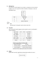
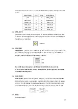
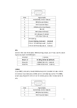
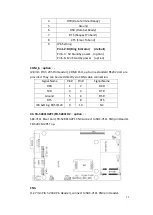
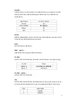
LED1, LED2 (option) :
LED1: LED STATUS. Green LED for Motherboard Standby Power Good status.
LED2: LED STATUS. Green LED for Touch Power status.
27.
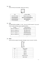
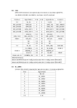
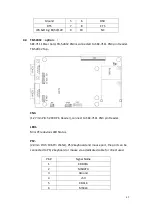
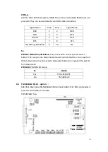
SATA_P:
(2.5mm Pitch 1x2 box Pin Header), One onboard 5V output connector are
reserved to provide power for SATA devices.
Pin#
Signal Name
1
+DC5V
2
Ground
Note:
Output current of the connector must not be above 1A.
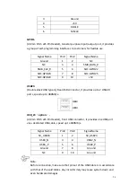
28. SATA2:
(SATA 7Pin), SATA Connectors, one SATA connector are provided, with transfer
speed up to 3.0Gb/s.
29. SATA1:
(SATA 7Pin+15Pin), SATA Connectors, one SATA connector are provided, with
transfer speed up to 3.0Gb/s.
30. SD1:
(SD card slot), Secure Digital Memory Card socket.
31. MPCIE1:
(Socket 52Pin), mini PCIe socket, it is located at the top, it supports mini PCIe
devices with USB2.0 and LPC and SMBUS and PCIe signal. MPCIe card size is
30x50.95mm.
32. H1/H2:
MPCIE1 SCREW HOLES, H1and H2 for mini PCIE card (30mmx50.95mm)
assemble.
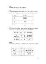
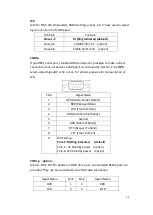
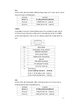
33. F_AUDIO1:
(2.0mm Pitch 2X6 Pin Header), Front Audio, An onboard Realtek ALC662-VD
codec is used to provide high-quality audio I/O ports. Line Out can be
connected to a headphone or amplifier. Line In is used for the connection of
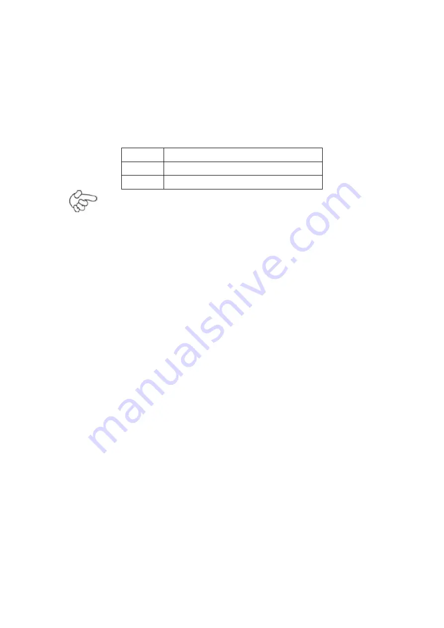
Содержание PC9 A Series
Страница 12: ...11 1 3 Dimensions Figure 1 1 Dimensions of PC9070 Figure 1 2 Dimensions of PC9080...
Страница 13: ...12 Figure 1 3 Dimensions of PC9101 Figure 1 4 Dimensions of PC9120...
Страница 14: ...13 Figure 1 5 Dimensions of PC9150A Figure 1 6 Dimensions of PC9156A Resistive Touch...
Страница 15: ...14 Figure 1 7 Dimensions of PC9156A Projected Capacitive Touch Figure 1 8 Dimensions of PC9170A...
Страница 16: ...15 Figure 1 9 Dimensions of PC9185A Figure 1 10 Dimensions of PC9215A Resistive Touch...
Страница 17: ...16 Figure 1 11 Dimensions of PC8215A Projected Capacitive Touch...
Страница 19: ...18 Figure 1 13 Rear View of PC9170 9180 Figure 1 14 Rear View of PC9101...
Страница 20: ...19 Figure 1 15 Rear View of PC9120 Figure 1 16 Rear View of PC9150A...
Страница 21: ...20 Figure 1 17 Rear View of PC9156A Figure 1 18 Rear View of PC9170A...
Страница 22: ...21 Figure 1 19 Rear View of PC9185A Figure 1 20 Rear View of PC9215A...
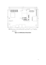
Страница 32: ...31 units mm Figure 2 1 Motherboard Dimensions...
Страница 63: ...62 3 3 Main Settings System Time Set the system time the time format is Hour 0 to 23 Minute 0 to 59...
Страница 83: ...82 Step 3 Read license agreement Click Yes Step 4 Click Next...
Страница 84: ...83 Step 5 Click Install Step 6 Click Install...
Страница 85: ...84 Step 7 Click Next Step 8 Click Yes I want to restart this computer now Then click Finish...
Страница 88: ...87 Step 5 Click Install to begin the installation Step 6 Click Finish to exit the wizard...
Страница 90: ...89 Step 3 Click Yes I want to restart my computer now Click Finish to complete the installation...
Страница 92: ...91 Step 3 Read the license agreement Then click Yes to continue Step 4 Click Next to continue...
Страница 95: ...94 Step 2 Select Resistive Touch Step 3 Click Next to continue...
Страница 97: ...96 Step 6 Wait for installation Then click Next to continue Step 7 Click Continue Anyway...
Страница 99: ...98 Step 2 Select Projected Capacitive Step 3 Click Next to continue...
Страница 100: ...99 Step 4 Select I accept the terms of the license agreement Click Next Step 5 Click Install RS232 interface driver...
Страница 101: ...100 Step 6 Select None Click Next Step 7 Click OK Step 8 Click Support Muti Monitor System Click Next...
Страница 102: ...101 Step 9 Go to C Program Files eGalaxTouch Click Next Step 10 Click Next...
Страница 109: ...108 About This panel displays information about the PenMount controller and driver version...
Страница 120: ...119 Hardware Saturn Hardware Configuration...
Страница 121: ...120 About To display information about eGalaxTouch and its version...


