3C
2. Technical Specifications
y
It can be operated by DMX512 control or can be used as an individual unit without
controller.
y
It can be linked together as many as required in master/slave mode, and perform the
great built-in programmed lighting shows triggered by music.
y
Please use a 3 pin XLR cable/plug when connecting them together.
y
It features different pre-programmed chase patterns.
y
Fan
cooled.
y
Channels
Channel 1 = Mode
Channel 2 = Pattern/Chase
Channel 3 = Pattern Strobe/Chase Speed
Channel 4 = Dimmer
y
Power supply
Input Voltage
:
100V-240V~50-60Hz
Power consumption
:
18W
y
LED
Total 156pcs, Red 48pcs, Green 36pcs, Blue 36pcs, White 36pcs
y
Dimension
:
300 x 308 x 280mm
y
Weight
:
4.2KG
3. Main Function
To select any functions, press
MENU
button until the required one is shown on the display.
Select the function by
ENTER
button and the display will blink. Use
DOWN
and
UP
button to
change the mode. Once the required mode has been selected, press
ENTER
button to
setup or it will automatically return to the main functions without any change after idling 8
seconds. Back to the functions without any change press
MENU
button. The main functions
are shown below:
8C
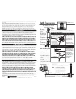
6. DMX512 Connections
The DMX512 is widely used in intelligent lighting control, with a maximum of 512 channels.
1. Connect the fixture together in a “daisy chain” by XLR plug cable from the output of the
fixture to the input of the next fixture. The cable cannot be branched or split to a “Y”
cable. Inadequate or damaged cables, soldered joints or corroded connectors can
easily distort the signal and shut down the system
2. The DMX output and input connectors are pass-through to maintain the DMX circuit
The DMX output and input connectors are pass-through to maintain the DMX circuit
when one of the units’ power is disconnected.
3. At last fixture, the DMX cable has to be terminated with a terminator to reduce signal
errors. Solder a 120-ohm 1/4W resistor between pin 2(DMX-) and pin 3(DMX+) into a
3-pin XLR-plug and plug it in the DMX-output of the last fixture.
4. Each lighting fixture needs to have an address set to receive the data sent by the
controller. The address number is between 0-511 (usually 0 & 1 are equal to 1).
5. 3 pin XLR connectors are more popular than 5 pins XLR.
3 pin XLR: Pin 1: GND, Pin 2: Negative signal (-), Pin 3: Positive signal (+)
5 pin XLR: Pin 1: GND, Pin 2: Negative signal (-), Pin 3: Positive signal (+),
Pin4/5: Not used.