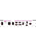
CONNECTORS
The device contains 5 connectors:
-
One male M12 connector for the two power supply sources, DC 9-75V,
7 W min
Pin
Signal
Name
Colour
3 Vdc
Blue
Power 1
4
GND
Black or Yellow
1 Vdc
Brown
Power 2
2 GND
White
5-point M12 Male
connector
5
NC
-
Two M12 connectors for LAN1 and LAN2 interfaces.
For WLg-ABOARD /N only
D-coded (4-point) M12
female connector
Signal Name
Pin 1:
TD+
Pin 2:
RD+
Pin 3:
TD-
Pin 4:
RD-
For WLg-ABOARD /NP (POE version) only
8-point M12 male
Connector
Signal Name
Pin 1:
PoE+
Pin 2:
PoE-
Pin 3:
PoE-
Pin 4:
TD-
Pin 5:
RD+
Pin 6:
TD+
Pin 7:
PoE+
Pin 8:
RD-
The two Ethernet ports LAN1 and LAN2 are auto-sensing (10 Base-T or 100
Base-Tx Half/Full Duplex) and self-configuring to allow connection via either a
cross-over or straight-through cable.
-
Two Female N-type antenna connectors.
Female N-type connector
Main connector: Main antenna used for Tx/Rx
Wlan activity.
Aux connector: Auxiliary antenna, when used
with Main antenna, operates according to
diversity mode.
If you don’t plug the Auxiliary antenna, you must
plug a 50 Ohms N-type antenna terminator (0-6
GHz) (ref:
WLg-ANT-TERM-N
)
-8-