Automation Components, Inc.
2305 Pleasant View Road | Middleton, WI 53562
Phone:
1-888-967-5224 |
Website:
workaci.com
Page 1
Version: 6.0
I0000701
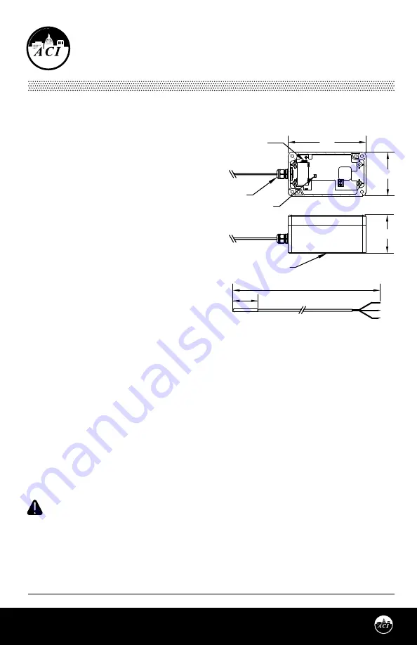
FIGURE 1:
ENCLOSURE DIMENSIONS
WIRELESS REMOTE/STRAP-ON
TEMPERATURE SENSORS
Installation & Operation Instructions
SST5630
Phone:
1-888-967-5224
Website:
workaci.com
the data transmission has been received successfully. The Data-Link LED will continue to blink once for
every data transmission. The data transmission rate is programmed into the sensor (normally 75 second
intervals). To manually initiate a data transmission press the push button switch located by the negative
terminal of the battery.
MOUNTING INSTRUCTIONS
ENCLOSURE MOUNTING
The enclosure must be mounted outside of the freezer/cooler. On Vertical units, mount on the top of the
freezer see
Figure 2
. On Horizontal units, mount on the backside or side of the freezer. Attach the base
directly to the wall by using double sided tape.
WIRE INSTALLATION
ACI recommends installing the wire through the
door seal, probe access port, or cooler wall. On
horizontal units, the preferred method is using the
rear door seal as shown in
Figure 3
. On vertical
units, remove the rear panel. There is typically a
probe access hole. Probe and wires can be ran into
that access hole. Alternatively, you can drill a hole
just larger than the diameter of the wire (0.125”
(3.175 mm)) through the wall. From inside the
cooler/freezer, push the wire through the hole. Use
mounting clips to secure the wire to the interior wall
or shelving. Use silicone caulking to seal the hole
around the wire.
2.56"
4.53"
2.23"
Battery Positive
Terminal
Internal Link
Button
SST5630AE
Altech Water
Tight Fitting
NEMA 4X Enclosure
10' Cable
2.00" x 0.187" Probe
GENERAL INFORMATION
The SST5630 is a battery operated spread spectrum
wireless remote/strap-on temperature sensor. It is
designed for monitoring refrigeration or freezers
from -300°F (-184°C) to 300°F (149°C).
The RTD sensor is encapsulated in a 0.187” O.D. 304
stainless steel probe (2” probe length) for single
point pipe temperature monitoring.
ACI’s wireless sensors utilize reliable Spread
Spectrum Radio technology. They can be installed
easily in minutes eliminating hundreds of feet of
wire and saving installation cost while reducing
installation labor risks.
The sensor Data-Link LED confirms the data
transmission was received by the receiver for fast
and reliable positioning of the sensor during
installation. There is no need for special wireless installation equipment or tool.
Together with the ACI receivers and controllers, the ACI wireless sensors can be used with any LON works,
BACnet, Modbus, system or panel.
The maximum radio transmission distance is dependent on the building type. In a typical commercial
building with steel I-Beam construction, concrete floors with reinforcing rod, and metal stud walls, it can be
expected that transmissions will penetrate vertically typically one floor below and one floor above a
transceiver/receiver, and horizontally through 200 to 300 feet of walls, furniture and air.
MOUNTING INSTRUCTIONS
Wireless sensors should be installed within 200 to 300 feet of the receiver. RR2552 signal repeaters can be
installed as to increase transmission distance between sensors and receivers.
CAUTION:
Observe battery polarity when installing battery.
To select the proper sensor location, first install and power the receiver. To activate the sensor insert the
battery observing the polarity.
While the sensor is attempting to connect to the receiver the Data-Link LED will blink rapidly 8–10 times
every 10 seconds. Once a connection has been established the Data-Link LED will blink once to indicate
SENSOR MOUNTING
Bullet Probe sensors can be wrapped around a shelf as
shown in
Figure 4
(p.2). Alternatively, the sensor
may be mounted on walls using a mounting clip. The sensor should be mounted in an area where air
circulation is well-mixed and not blocked by obstructions. Slide the sensor probe through the mounting
clip - see
FIGURE 5 (p.2).
Drill a 1/4” screw through the socket and tighten to the wall. If a thermal buffer is
required, use a glycol kit (ACI Item #130127). Drill pilot holes for the provided mounting screws. Use the
mounting clip holes as a guide - see
FIGURE 6
(p.2). Drill the #10-16 x 1/2“ screws through the bracket
holes and fasten it to the wall. Insert the bottle into the bracket, and make sure it is seated securely.
Note:
When using in tank or glycol application, the sensor cannot be fully submerged. The back end of the
probe (where the wire enters), must be kept above the liquid.
Locate and record the sensor ID numbers located on a label inside the unit prior to mounting.
The sensor has a Low Battery LED that will start to blink continuously when the battery voltage is low. A
low battery signal is also sent to the receiver for remote indication that the battery should be replaced. If
the battery is not replaced in approximately 2 months, the battery voltage will become so low that the Low
Battery and Data-Link LEDs will not blink. Replace the battery and the Data-Link LED will start blinking
while the sensor is re-establishing communications with the receiver.
Then attach the cover of the sensor by installing the four screws.
PRECAUTIONS
SENSORS, REPEATERS AND RECEIVERS SHOULD NOT BE INSTALLED IN THE FOLLOWING AREAS:
• INSIDE METAL ENCLOSURE / PANEL
• INSIDE OR IMMEDIATELY NEXT TO ELEVATOR SHAFT / ELEVATOR BANKS
• IN FRONT OF OR IMMEDIATELY NEXT TO LARGE TREES OR LARGE BODY OF WATER
TRANSMISSION DISTANCE AND PERFORMANCE WILL BE DRASTICALLY REDUCED.
CAUTION:
DO NOT USE THIS PRODUCT IN ANY SAFETY RELATED APPLICATIONS WHERE HUMAN LIFE
MAY BE AFFECTED.


