Page 6
PAR 2
0
0
1
1
PAR 1
0
1
0
1
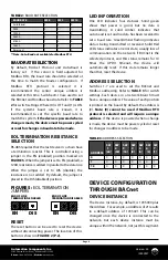
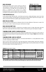
Mode (Databits-Parity-Stop Bits)
8-Even-1
8-Odd-1
8-None-2
8-None-1 (Non-Standard)
TABLE 6:
PARITY AND STOP BITS
Automation Components, Inc.
2305 Pleasant View Road | Middleton, WI 53562
Phone:
1-888-967-5224 |
Website:
workaci.com
1001
0 = Disable Test Mode. IR3 and IR4 will read with current Sensor
Value.
1 = Enable Test Mode. IR3 and IR4 will read with the values stored
in HR1001 and HR1002 .
Test Mode Enable
1000
REFERENCE
DESCRIPTION
NAME
ADDRESS
1
2
3
4
For each bit location:
0 = Sensor not present
1 = Sensor present
Bit 0 - Temperature Sensor
Bit 1 - RH sensor
N/A
For example, a value of 312 would represent 31.2 Degrees of the
units selected in HR1. Signed Integer.
For Example: A value of 429 would represent 42.9% Relative
Humidity.
Sensors Present
Reserved
Temperature Sensor
Value
RH Sensor Value
0
1
2
3
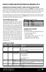
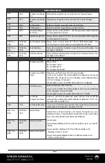
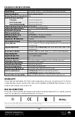
MODBUS RTU MAP
DEVICE CONFIGURATION THROUGH MODBUS RTU
MODBUS RTU DATABITS, PARITY, AND STOP BITS SELECTION
Confirm Modbus Protocol is selected via dipswitch #4 on SW4 - see
FIGURE 4
. The device that requests
information is called the Modbus Master and the devices giving the information are Modbus Slaves. The
Modbus sensors are slave devices and the number of Data Bits needs to be the same as in the Master
device configuration. ACI’s Modbus RTU sensors utilize 8 data bits during communication exchange.
Parity and stop bit selection is performed via the SW4 switch located on the board. Dipswtiches #1 and #2
are adjusted to select the parity and stop bits - see
TABLE 6
. Where (0) is OFF and (1) is ON. If BACnet
protocol is selected these dipswitches are irrelevant.
TEST MODE Modbus RTU
There are 5 data values in test mode. Coil 1001,
Holding Registers (HR) 1001 and 1002, and the
Input Registers (IR) 0003 and 0004 for Temp and
RH values. When Coil 1001 is enabled, reading IR
0003 and 0004 will respond with the values in HR
1001 and 1002, other wise they will respond with
the actual sensor values. General process for this
is to write initial test values to HR 1001 and 1002,
Enable Coil 1001 and then read as normal from IR
0003 and 0004. While Coil 1001 is enable, it is
possible to write a change of value to IR 1001 and
1002, which will be reflected in the next read from
IR 0003 and 0004. When testing completed,
disable Coil 1001. The status of Coil 1001 and HR
1001 and 1002 are not persistent between
reset/power cycle.
MODBUS RTU MODEL
Modbus data model:
Four (4) primary data tables (addressable registers)
• Discrete Input (read only bit).
• Coil (read / write bit).
• Input register (read only 16 bit word,
interpretation is up to application).
• Holding register (read / write 16 bit word).
INPUT REGISTER (IR)
Version: 2.0
I0000927
COILS (CL)

