59
No
Yes
No
Yes
No
No
No
Yes
Yes
Yes
Yes
Chapter 4 Troubleshooting
System Analysis
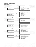
Keypad LED OK
If Power On, Lamp On?
No Signal?
Power Auto Turn Off
IR Remote Control NG?
Pixel Fail?
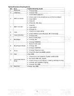
Step:
1.
Check Lamp Door
2.
Check Power Board and Interlock
3.
Check Connection between PWR BD
and Main BD
4.
Check Main Board
1.
Check Lampen wire , Lamp wire and
Ballast wire
2.
Check C/W and wire connection
3.
Check Main board
4.
Check Lamp
5.
Check Ballast
1.
Check Input Cable
2.
Check OSD Source set up
3.
Check Main board
1.
Check OSD Lamp Hours
2.
Check Lamp Door
3.
Check Lamp still light or not?
4.
Check Fan still spin or not?
5.
Check Thermal status
1.
Check Remote module battery
2.
Check Remote module
3.
Check IR Receiver on Main board
4.
Check IR Receiver on IR board
1.
Check the connection between Main
BD and Chip BD
2.
Check the connection between OP
engine and DMD Chip
3.
Check Chip board
4.
Check Main board
Содержание X1230S Series
Страница 16: ...16 Product Overview...
Страница 17: ...17...
Страница 18: ...18...
Страница 19: ...19...
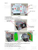
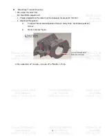
Страница 39: ...39 Fig 1 3 Fig 1 4 1 Press down the Clip 2 Insert the LP Module Overfill adjustment screws LP Datum of DMD HSG...
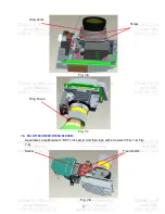
Страница 42: ...42 Fig 3 3 Fig 3 4 Fig 3 5 Fig 3 6 Datum1 Datum2 Datum3 Clip UP CM Sponge...
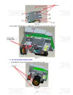
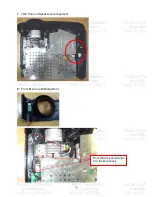
Страница 53: ...53 This cord location is here First assy Blower module Second assy Mylar Ballast...
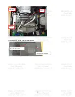
Страница 54: ...54 3 Blower wire alignment This clip must be screwed by this direction...
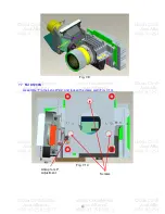
Страница 58: ...58 11 Lamp Door screw assemble sequence First Second Third...
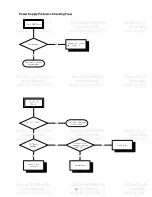
Страница 62: ...62 Power Supply Problems Checking Flow...
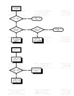
Страница 63: ...63...
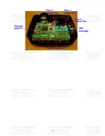
Страница 65: ...65 Fan 1 Lamp Fan Fan 2 Power Fan Fan 3 Blower Fan Thermal sensor 2 Thermal sensor 1 LED message...
Страница 76: ...76...
Страница 77: ...77 Module 2 ASSY UPPER CASE...
Страница 78: ...78 Module 3 ASSY LOWER CASE...
Страница 79: ...79 Module 4 ASSY FRONT CASE...

