33
Chapter 3 System Disassembling and Replacement
Main Unit Disassembling
Tool :
Screw Driver --Hex (#4-40) and Cross(Mechanical : M3,M4, Opt.Engine :M2)
Process :
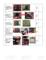
Step Discription
Tool
Notice
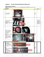
1
Disassemble the
screw*5(M3*7L).
screw
driver
2
(1) Take off the the IR
sensor wire from
mainboard,
(2) Take off upper case
module.
When taking
off upper
case module,
be careful not
to break the
IR-M/B wire.
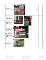
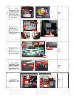
3
(1) Take off the case
outlet case module
(2) Take off the front
case module
(3) (For
X1230/X1230S/X1230S/
X1230K):
Take off the screw*4
(M3*7L) and speaker
from the outlet case
module
screw
driver
keypad bracket
2
1
3
4
5
FRONT
IR BD
1
2
4
3
keypad Rubber
Three long sponge
Two sponge
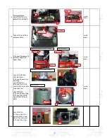
4
<For X1130> :
Disassemble the
screw*2(STAND OFF
XH4#-40), and take off
the rear case.
<For
X1230/X1230S/X1235/X
1230K> :
Disassemble the
screw*4(STAND OFF
XH4#-40), and take off
the rear case.
screw
driver
rear case
1
2
3
4
rear case
1
2
Содержание X1230S Series
Страница 16: ...16 Product Overview...
Страница 17: ...17...
Страница 18: ...18...
Страница 19: ...19...
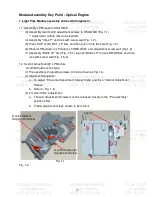
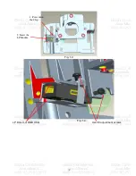
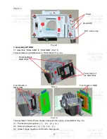
Страница 39: ...39 Fig 1 3 Fig 1 4 1 Press down the Clip 2 Insert the LP Module Overfill adjustment screws LP Datum of DMD HSG...
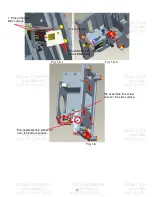
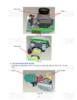
Страница 42: ...42 Fig 3 3 Fig 3 4 Fig 3 5 Fig 3 6 Datum1 Datum2 Datum3 Clip UP CM Sponge...
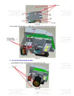
Страница 53: ...53 This cord location is here First assy Blower module Second assy Mylar Ballast...
Страница 54: ...54 3 Blower wire alignment This clip must be screwed by this direction...
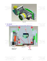
Страница 58: ...58 11 Lamp Door screw assemble sequence First Second Third...
Страница 62: ...62 Power Supply Problems Checking Flow...
Страница 63: ...63...
Страница 65: ...65 Fan 1 Lamp Fan Fan 2 Power Fan Fan 3 Blower Fan Thermal sensor 2 Thermal sensor 1 LED message...
Страница 76: ...76...
Страница 77: ...77 Module 2 ASSY UPPER CASE...
Страница 78: ...78 Module 3 ASSY LOWER CASE...
Страница 79: ...79 Module 4 ASSY FRONT CASE...

