background image

Chapter 3

31

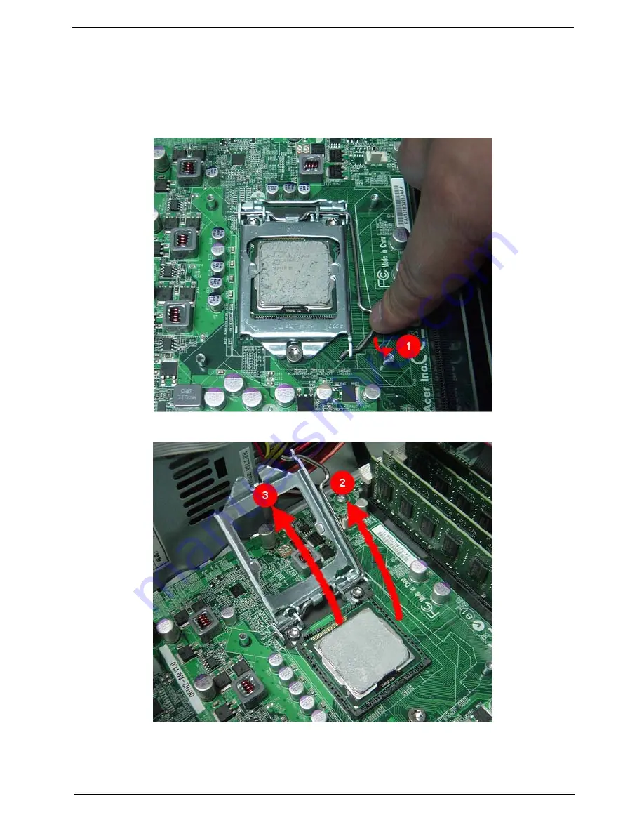
Removing the Processor

IMPORTANT:

Before removing a processor from the mainboard, make sure to create a backup file of all 
important data. 

WARNING:

The processor becomes very hot when the system is on. Allow it to cool off first before handling. 

1.

Release the load lever(1).

2.

Lift the load lever and load plate to the fully open, upright position (2)


and (3).

Содержание Veriton M4618G

Страница 1: ...Acer Veriton M4610 M4610G M4618G Service Guide PRINTED IN TAIWAN...

Страница 2: ...ii Revision History Please refer to the table below for the updates made on this service guide Date Chapter Updates...

Страница 3: ...blication may be reproduced transmitted transcribed stored in a retrieval system or translated into any language or computer language in any form or by any means electronic mechanical magnetic optical...

Страница 4: ...programs prove defective following their purchase the buyer and not Acer Incorporated its distributor or its dealer assumes the entire cost of all necessary servicing repair and any incidental or cons...

Страница 5: ...itional information related to the current topic WARNING Alerts you to any physical risk or system damage that might result from doing or not doing specific actions CAUTION Gives precautionary measure...

Страница 6: ...cases please contact your regional offices or the responsible personnel channel to provide you with further technical details FRU Information Please note WHEN ORDERING FRU PARTS that you should check...

Страница 7: ...Printer Port Cable and COM Port Cable 39 Removing the Intrusion Alarm and OBR Cable Cable 41 Removing the System FAN 43 Removing Other Side Pannel 45 Removing the Power Supply 46 Removing the Card Rea...

Страница 8: ...tem Check 82 System External Inspection 82 System Internal Inspection 82 Beep Codes 83 Checkpoints 84 BIOS Recovery 87 Jumper and Connector Information 88 M B Placement 88 Jumper Setting 90 Setting Ju...

Страница 9: ...ndow mode FreeDos Processor Socket Type LGA 1155 pin Socket Quantity 1 Processor Type Intel Sandy Bridge Processor 32 nm 2nd Generation Hi K metal gate process processor core 32nm Hi K metal gate proc...

Страница 10: ...Optical disk drive Support SATA 5 25 standard ODD Support DVD ROM DVD SuperMulti Label Flash BD DVD BD Combo BD RW Capacity and model is listed on AVLC Graphics Intel HD Graphics Support Dual independ...

Страница 11: ...io spec v4 1 audio C R should support Acer Internal speaker spec BIOS should meet MS Pin Configuration Guidelines for High Definition Audio Devices One earphone and one microphone jack is required on...

Страница 12: ...I Four 2 5 pin Intel FPIO specification USB pin connectors follow Intel FPIO standard Specification One 2 5 pin Intel FPIO spec Microphone In Headphone Out pin connectors One 4 pin CPU Fan connector O...

Страница 13: ...B 12V attention to 12V output capability Demand for both PFC Non PFC solutions two different quotations are needed Minimum 4 Serial ATA power connector solution should be included by default Minimum 1...

Страница 14: ...6 Chapter 1 Block Diagram...

Страница 15: ...r of the system s interior and exterior components Front Panel No Component 1 USB 2 0 ports 2 Acer logo 3 Optical drive 4 LAN activity indicator 5 Power button 6 HDD activity indicator 7 Headphone Spe...

Страница 16: ...3 Serial port 4 DVI D port 5 Display port 6 USB 2 0 ports 7 Line out jack 8 Microphone jack 9 Expansion slot graphics card ect 10 line in jack 11 Lock Handle 12 RJ45 LAN port 13 Parallel port 14 Seri...

Страница 17: ...OS ROM type SPI Flash BIOS ROM size 8Mb Support protocol SMBIOS DMI 2 4 DMI2 0 Device Boot Support 1st priority EFI device 1st priority EFI device 2nd priority SATA HDD 3rd priority CD ROM 4th priorit...

Страница 18: ...bination as long as they match the above specifications Item Specification Audio controller Intel Q65 Audio controller type ALC662 Audio channel codec 5 1 Audio function control Enable disable by BIOS...

Страница 19: ...ear ports USB2 0 6 ports On board 4 2 5 headers 8ports 4 ports for front daughter board 4 ports reserved Connector Pin standard Intel FPIO pin definition Item Specification Temperature Operating 5 C 3...

Страница 20: ...xternal switch Button modem ring in keyboard an mouse for APM mode Resume recovery time 7 10sec Suspend Mode Independent power management timer 2 120minutes time step 10minute or pushing extern switch...

Страница 21: ...ompted Run Setup message to make changes to the CMOS setup NOTE If you repeatedly receive Run Setup messages the battery may be bad In this case the system cannot retain configuration values in CMOS A...

Страница 22: ...age of a multiple page menu Home Move the cursor to the first page of a multiple page menu End Move the cursor to the last page of a multiple page menu and keys Select a value for the currently select...

Страница 23: ...BIOS setup utility was built Processor Type of CPU installed on the system Core Frequency Core speed of the CPU installed on the system Count Physical CPU count Memory Size Total size of system memor...

Страница 24: ...cess the Miscellaneous submenu Advanced Chipset Configuration Press Enter to access the Advanced Chipset Configuration submenu Integrated Peripherals Press Enter to access the Integrated Peripherals s...

Страница 25: ...to all DIMM PCI PCIE Enabled Disabled Spread Spectrum If you enable spread spertrum it can significantly reduce the EMI Electro Magneticinterface generated by the system and voltage according to its t...

Страница 26: ...code in the buffer preventing damage and worm propagation When disabled the processor forces the Execute Disable XD Bit feature flag to always return to 0 Enabled Disabled Intel VT Enables or disables...

Страница 27: ...oard audio controller Enabled Disabled Onboard LAN Controller Enables or disables the onboard LAN controller Enabled Disabled Onboard LAN Option ROM Enables or disables the load of embedded option ROM...

Страница 28: ...item enables or disables you to set the shutdown temperature of the system Enabled Disabled CPU Shutdown Temperature This item enables or disables you to set the shutdown temperature of the CPU Enabl...

Страница 29: ...there is an incoming call on the PCI LAN card You must use an ATX power supply in order to use this feature Use this item to dowake up action if inserting the PCI card Enabled Disabled Power on by Mod...

Страница 30: ...n use the sub menu to change the HDD password TPM Support This item is set to support TPM Trusted Platform Module funtion Enabled Disabled TPM State This item displays the TPM status to be enabled dis...

Страница 31: ...ss the Optical Disk Drive Priority submenu and specify the boot device priority sequence from available optical drives Removable Device Priority Press Enter to access the Removable Device Priority sub...

Страница 32: ...u and press Enter Save Changes Select this option and press Enter to save all the changes and return to the BIOS Setup Utility Discard Changes Use this item enables you to discard any changes that you...

Страница 33: ...tools Wrist grounding strap and conductive mat for preventing electrostatic discharge Flat blade screwdriver Philips screwdriver Hex screwdriver Plastic flat blade screwdriver Plastic tweezers NOTE T...

Страница 34: ...edure perform the steps listed below 1 Turn off the system and all the peripherals connected to it 2 Unplug the power cord from the power outlets 3 Unplug the power cord from the system 4 Unplug all p...

Страница 35: ...crews located on the rear edge of the side panel 2 The firstly use two fingers to Press the lock handle toward the arrowhead of the direction until the lock handle no moving then use other hand to Lif...

Страница 36: ...28 Chapter 3 Removing the Front Bezel 1 Remove the side panel Refer to the previous section for instructions 2 Release the front bezel from the chassis interior 3 Pull the bezel away from the chassis...

Страница 37: ...ink with any metal or with your hands 1 Disconnect the fan cable from the mainboard 2 Use a long nosed screwdriver to loosen the four screws on the heat sink in the order as shown below Note CPU Fan h...

Страница 38: ...the heat sink fan assembly then lay it down in an upright position with the thermal patch facing upward Do not let the thermal patch on the heat sink fan assembly touch the work surface 5 Use an alcoh...

Страница 39: ...he mainboard make sure to create a backup file of all important data WARNING The processor becomes very hot when the system is on Allow it to cool off first before handling 1 Release the load lever 1...

Страница 40: ...32 Chapter 3 3 Pull out the processor from the socket IMPORTANT If you are going to install a new processor note the arrow on the corner to make sure the processor is properly oriented over the socket...

Страница 41: ...finger to Press the clip and use another hand Gently pull the card to remove it from the mainboard Note Circuit boards 10 cm has been highlighted with the yellow rectangle as above image shows Please...

Страница 42: ...all important data 1 Press the holding clips on both sides of the DIMM slot outward to release the DIMM 1 2 Gently pull the DIMM upward to pull it away from the M B 2 Note Circuit boards 10 cm has bee...

Страница 43: ...Chapter 3 35 Removing the Hard Disk Drive 1 Disconnect the data and power cables from the rear of the optical drive 2 Disconnect the other end of the data cable from the mainboard...

Страница 44: ...two fingers to press the HDD bracket then lift the bracket up 4 Take out the HDD module a Use a hand to open out the HDD bracket until the hook of HDD bracket away from the HDD screw bore then use ot...

Страница 45: ...tical Drive 1 Disconnect the data and power cables from the rear of the optical drive 2 Disconnect the other end of the data cable from the mainboard 3 Slide two lock handle toward the left 1 until th...

Страница 46: ...38 Chapter 3 4 Push the rear of the optical drive take out the slave ODD 5 Use the same method to take out master ODD...

Страница 47: ...rinter Port Cable and COM Port Cable 1 Remove the printer port cable a Disconnect the printer port cable from motherboard b Remove the two screws according to the following picture c Pull the printer...

Страница 48: ...40 Chapter 3 2 Remove the COM port cable a Disconnect the COM port cable from motherboard b Remove the two screws as below c Pull the COM port cable form the chassis...

Страница 49: ...ng the Intrusion Alarm and OBR Cable Cable Assembly 1 Remove the intrusion alarm cable assembly a Disconnector the intrusion alarm cable from the motherboard b Removing the two screws c Pull the intru...

Страница 50: ...42 Chapter 3 2 Remove the OBR cable assembly a Disconnoct the OBR cable from the motherboard b Release the retention tabs from the chassis interior c Pull the OBR cable assembly from the chassis...

Страница 51: ...Chapter 3 43 Removing the System FAN 1 Remove System FAN cable from M B 2 Release four screws according to the following picture...

Страница 52: ...Chapter 3 3 Take off the system fan from chassis Note System fan has been highlighted with the yellow rectangle as above image shows Please detach the system fan and follow local regulations for dispo...

Страница 53: ...Chapter 3 45 Removing Other Side Pannel 1 Remove the two screws located on the rear edge of the side panel 2 Lift the side panel away from the server...

Страница 54: ...Chapter 3 Removing the Power Supply 1 Release the HDD power cable from the clip and release the HDD power cable in back of chassis 2 Disconnect the 4 pin and 24 pin power supply cables from the mainbo...

Страница 55: ...Chapter 3 47 3 Remove the four screws that secures the power supply to the chassis 4 Lift the power supply module out of the chassis...

Страница 56: ...e Card Reader 1 Disconnector the card resder cable from the motherboard then release the card reader and internal speaker cable from the clip 2 Slide the lock handle as show below 3 Pull the card read...

Страница 57: ...Chapter 3 49 Removing the Internal Speaker 1 Disconnector the speaker cable from the motherboard 2 Slide the lock handle as show below 3 Pull the internal speaker away from bracket...

Страница 58: ...Audio USB cable from the mainboard 2 Remove the eight screws that secure the mainboard to the chassis Note Circuit boards 10 cm has been highlighted with the yellow rectangle as above image shows Plea...

Страница 59: ...he chassis 4 Punching in IO Shield then you can remove it 5 Remove the RTC battery Note RTC battery has been highlighted with the yellow circle as above image shows Please detach the RTC battery and f...

Страница 60: ...52 Chapter 3 Removing the Front I O and USB Assembly 1 Release the cable from clip 2 Release the five locking tabs from the chassis interior 3 Lift the front I O and USB cover from the chassis...

Страница 61: ...Chapter 3 53 4 Removing the screws from the chassis 5 Lift the front I O and USB assembly away from chassiss...

Страница 62: ...54 Chapter 3 Removing the Power Switch and LED Cable Assembly 1 Release the locking tabs from the chassis interior 2 Pull the power switch and LED cable assembly from the chassis...

Страница 63: ...r preventing electrostatic discharge Flat blade screwdriver Philips screwdriver Hex screwdriver Plastic flat blade screwdriver Plastic tweezers NOTE The screws for the different components vary in siz...

Страница 64: ...perform the steps listed below 1 Turn off the system and all the peripherals connected to it 2 Unplug the power cord from the power outlets 3 Unplug the power cord from the system 4 Unplug all periph...

Страница 65: ...e load lever and load plate to the fully open then take out the CPU cover 3 Put the CPU in the seat and close the load plate and load lever NOTE When you install the processor note the arrow on the co...

Страница 66: ...olding clips on both sides of the DIMM slot outward 2 Press down the memory IMPORTANT pls refer to below installing memory rule DIMM1 DIMM2 DIMM3 DIMM4 A A B A A B A B A B A A A A B A A A B Remark A a...

Страница 67: ...Chapter 3 59 Install the Heat Sink Fan Assembly 1 Use a long nosed screwdriver to fix the four screws on the heat sink in the order as shown below 2 Connect the fan cable to the mainboard...

Страница 68: ...he both Side Panel 1 Remove the four screws located on the rear edge of the side panel 2 Lift the side panel away from the server and put it aside for reinstallation later 3 Use the same way to remove...

Страница 69: ...Chapter 3 61 Install the I O Shielding 1 Install I O shielding into chassis...

Страница 70: ...assis aligning the M B I O connector with I O shielding 2 Fix1 8 pcs screws into the corresponding hole NOTE Make sure the I O spring touching M B after installing 3 Connector the Power switch Top USB...

Страница 71: ...Chapter 3 63 4 Connect the ATX 24Pin Power cable and ATX 4Pin Power cable to main board...

Страница 72: ...64 Chapter 3 Install the System FAN 1 Tie system fan cable 2 Push the system fan to chassis...

Страница 73: ...Chapter 3 65 3 Fix the four screws 4 Connect the system fan power cable to Main board...

Страница 74: ...nel frist whether there is the panel of ODD if so shall panel of ODD disassembly from the front panel At the same time check ODD location whether there is the sheet metal if so remove the sheet metal...

Страница 75: ...Chapter 3 67 5 Close the Lock handle 6 Connect the power cables and data cable to the rear of the optical drive 7 Connect the other end of the data cable to the mainboard...

Страница 76: ...f so shall panel of 3 5 card disassembly from the front panel At the same time check 3 5 card location whether there is the sheet metal if so remove the sheet metal 2 When prepare to install the 3 5 c...

Страница 77: ...Chapter 3 69 b Connect the card reader cable to main board 4 Install the internal speaker a Push the internal speaker to chassis b Connect the internal speaker cable to main board...

Страница 78: ...70 Chapter 3 5 Close the lock handle IMPORTANT Install the 3 5 Card rule...

Страница 79: ...r 3 71 Install the the COM Port Cable and Printer Port Cable 1 Install the COM port cable a Push the COM port cable to chassis b Fix the two screws as shown below c Connect the COM port cable to main...

Страница 80: ...72 Chapter 3 2 Install the printer port cable a Push the printer port cable to the chassis then fix the two screws according to the following picture b Connect the printer port cable to motherboard...

Страница 81: ...acket from chassis Hook of HDD bracket as shonw below 2 Shall the HDD power cable through clip and chassis hole and fix the power cable to clip 3 Open out the HDD bracket install the HDD NOTE The hook...

Страница 82: ...nstall master HDD into slot 1 a Use two fingers to press the HDD bracket then Install Master HDD into slot 1 5 Ues the same way to install the slave HDD into slot 2 6 Shall the HDD data cable through...

Страница 83: ...Chapter 3 75 7 Connect the data cable and power cable to the rear of the hard disk drive 8 Connect the HDD data cable to main board...

Страница 84: ...76 Chapter 3 Install the Right Side Panel 1 Install the side Panel then fix two Screws...

Страница 85: ...Chapter 3 77 Install the VGA Card 1 Remove the PCI fixer 2 Remove the PCI slot...

Страница 86: ...78 Chapter 3 3 Open the VGA card latch then press down the VGA card 4 Close the PCI fixer...

Страница 87: ...Chapter 3 79 Install the Front Bezel 1 Install the panel onto chassis and then check if it is Installed OK...

Страница 88: ...80 Chapter 3 Install the Lift Side Panel 1 Connect the OBR cable and Intrusion cable to main board 2 Install the side Panel then fix two Screws...

Страница 89: ...cerproducts prototype cards or modified options can give false errors and invalid systemresponses 1 Obtain the failing symptoms in as much detail as possible 2 Verify the symptoms by attempting to rec...

Страница 90: ...tem Internal Inspection System Internal Inspection 1 Turn off the system and all the peripherals connected to it 2 Unplug the power cord from the power outlets 3 Unplug the power cord from the system...

Страница 91: ...d has been activated Not all computers using AMIBIOS enable this feature In most cases a checkpoint card is the best tool for viewing AMIBIOS checkpoints Beep Symptom Cause and Description One short b...

Страница 92: ...critical initialization Early chipset initialization is done D1 Early super I O initialization is done including RTC and keyboard controller Serial port is enabled at this point if needed for debuggin...

Страница 93: ...heckpoints section of document for more information DC System is waking from ACPI S3 state E1 E8 EC EE OEM memory detection configuration error This range is reserved for chipset vendors system manufa...

Страница 94: ...loppy EA Enable ATAPI hardware Attempt to read from ARMD and ATAPI CDROM EB Disable ATAPI hardware Jump back to checkpoint E9 EF Read error occurred on media Jump back to checkpoint EB F0 Search for p...

Страница 95: ...The following is the process that user should follow to flash BIOS ROM 1 Put the AMIBoot ROM to a bootable USB flash drive Disk on Key DOK 2 Install the DOK to the system 3 Press power button to boot...

Страница 96: ...Chapter 5 88 M B Placement Jumper and Connector Information Chapter 5...

Страница 97: ...11 SATA1 Serial ATA 6 0 Gb s connectors Red color compatible with SATA 2 0 12 SATA3 6 Serial ATA 3 0 Gb s connectors Black color 13 BIOS_WP BIOS write protecting jumper 14 F_PANEL Front panel switch L...

Страница 98: ...etting the jumpers ensure that the jumper caps are Placed on the correct pins The illustrations show a 2 pin jumper Whenthe jumper cap is placed on both pins thejumper is SHORT If you remove the jumpe...

Страница 99: ...iption Setting default CLR_CMOS 3 pin CLEAR CMOS 1 2 NORMAL 2 3 CLEAR Before clearing the CMOS make sure to turn the system off CLR_CMOS ME_DISABLE 3 pin Disable ME 1 2 NORMAL 2 3 ME disable BIOS_WP 3...

Страница 100: ...O Front Panel Audio heade This header allows the user to install auxiliary front oriented microphone and line out ports for easier access Pin Signal Name Pin Signal Name 1 PORT F_L 2 AUGND 3 PORT F_R...

Страница 101: ...eaders supporting four USB 2 0 ports Addition ally some computer cases have USB ports at the front of the case If you have thiskind of case use auxiliary USB connector to connect the front mounted por...

Страница 102: ...ecification detailing amicrocontroller that can store secured information and implementations of that specification Pin Signal Name 1 VCC 2 KEY 3 SPDIFOUT 4 GND Pin Signal Name Function 1 DCD Data Car...

Страница 103: ...board parallel port header Pin1 2 Signal Name Short Chassis cover is removed Open Chassis cover is closed Pin Signal Name Pin Signal Name 1 Output_L 2 GND 3 Output_R 4 Key 5 GND 6 GND 7 N A 8 VCC Pin...

Страница 104: ...N CPU cooling FAN Power Connector SYS_FAN System Cooling FAN Power Connector Pin Signal Name Function 1 GND System Ground 2 12V Power 12V 3 Sense Sensor 4 CONTROL CONTROL Pin Signal Name Function 1 GN...

Страница 105: ...1 3 3V 13 3 3V 2 3 3V 14 12V 3 COM 15 COM 4 5V 16 PS_ON 5 COM 17 COM 6 5V 18 COM 7 COM 19 COM 8 PWR OK 20 5V 9 5VSB 21 5V 10 12V 22 5V 11 12V 23 5V 12 3 3V 24 COM Pin Signal Name 1 Ground 2 Ground 3 1...

Страница 106: ...l NOT be noted on the printed Service Guide For Acer authorized service providers your Acer office may have a different part number code from those given in the FRU list of this printed Service Guide...

Страница 107: ...5 USB PCB MODULE 1 22 USB TOP 1 6 SIDE FOOT RUBBER 4 23 LOGO SUPPORT 1 7 RIGHT SIDE PLATE 1 24 MAIN BEZEL 1 8 LED SEITCH HOLDER 1 25 LEFT WIRE NETTING 1 9 CD ROM 1 26 ODD COVER 2 10 CARD READER DEVICE...

Страница 108: ...zel New Veriton Bezel VM410 for HM081 PZ 11900 077 N A Nameplate Nameplate M6 series TBD N A Dust filter Dust filter_HM081 for HM081 V 2 Flammability Rating PC 13400 027 N A CPU Cooler Cooler Intel LG...

Страница 109: ...5 7200rpm 160GB HDS721016CLA382 Jupiter SATA II 8MB LF F W 3EA KH 16007 027 16 HDD HGST 3 5 7200rpm 320GB HDS721032CLA362 Jupiter SATA II 16MB LF F W 3EA KH 32007 011 HDD HGST 3 5 7200rpm 500GB HDS72...

Страница 110: ...II TBD HDD WD 3 5 7200rpm 1000GB SATA III TBD ODD ODD HLDS DVD ROM HH DL 16X DH40N LF HF Black Bezel HF Win7 SATA KV 0160D 017 9 ODD PLDS DVD ROM HH DL 16X DH 16D5SH LF HF Black Bezel SATA w Win7 KV 0...

Страница 111: ...ealteck_5181 w micro SD w M2 CR 10400 097 10 16 in 1 CR RI730 UT330 LK 510mm USB cable for Commercial 30L housing CR 10400 112 Modem Lite On PCI Modem card D 1156I A7A LSI Universal Modem PCI 56K V 92...

Страница 112: ...r Port Cable W O ATX bracket PA V6000 002 N A COM port cable COM2 Cable with shielding w o ATX bracket 470mm PC 13400 050 N A PCGuard Recovery Card PCGuard V5 package with CD Quick Guide PCI Full Heig...

Страница 113: ...B PS203 292 Keyboard CHICONY KB 0759 PS 2 Standard 107KS Black Brazilian Portuguese w o eKey KB PS203 293 Keyboard CHICONY KB 0759 PS 2 Standard 105KS Black German w o eKey KB PS203 295 Keyboard CHICO...

Страница 114: ...tandard 105KS Black Spanish Latin w o eKey KB PS203 316 Keyboard CHICONY KB 0759 PS 2 Standard 105KS Black Turkish Q w o eKey KB PS203 317 Keyboard CHICONY KB 0759 PS 2 Standard 105KS Black Arabic Fre...

Страница 115: ...KB PS20B 077 Keyboard LITE ON SK 9620 PS 2 Standard 107KS Black Brazilian Portuguese w o eKey KB PS20B 078 Keyboard LITE ON SK 9620 PS 2 Standard 105KS Black German w o eKey KB PS20B 080 Keyboard LIT...

Страница 116: ...TE ON SK 9620 PS 2 Standard 105KS Black Spanish Latin w o eKey KB PS20B 101 Keyboard LITE ON SK 9620 PS 2 Standard 105KS Black Turkish Q w o eKey KB PS20B 102 Keyboard LITE ON SK 9620 PS 2 Standard 10...

Страница 117: ...ack German w o eKey KB USB03 203 Keyboard CHICONY KU 0760 USB Standard 105KS Black Italian w o eKey KB USB03 204 Keyboard CHICONY KU 0760 USB Standard 105KS Black French w o eKey KB USB03 205 Keyboard...

Страница 118: ...ONY KU 0760 USB Standard 105KS Black Arabic French w o eKey KB USB03 226 Keyboard CHICONY KU 0760 USB Standard 104KS Black Kazakh w o eKey KB USB03 227 Keyboard CHICONY KU 0760 USB Standard 104KS Blac...

Страница 119: ...ack German w o eKey KB USB0B 169 Keyboard LITE ON SK 9625 USB Standard 105KS Black Italian w o eKey KB USB0B 170 Keyboard LITE ON SK 9625 USB Standard 105KS Black French w o eKey KB USB0B 171 Keyboard...

Страница 120: ...190 Keyboard LITE ON SK 9625 USB Standard 105KS Black Turkish Q w o eKey KB USB0B 191 Keyboard LITE ON SK 9625 USB Standard 105KS Black Arabic French w o eKey KB USB0B 192 Keyboard LITE ON SK 9625 USB...

Отзывы: