


69
Chapter 3
4.
See “Removing the Power Board” on page 65.
5.
See “Removing the Upper Case Assembly” on page 65.
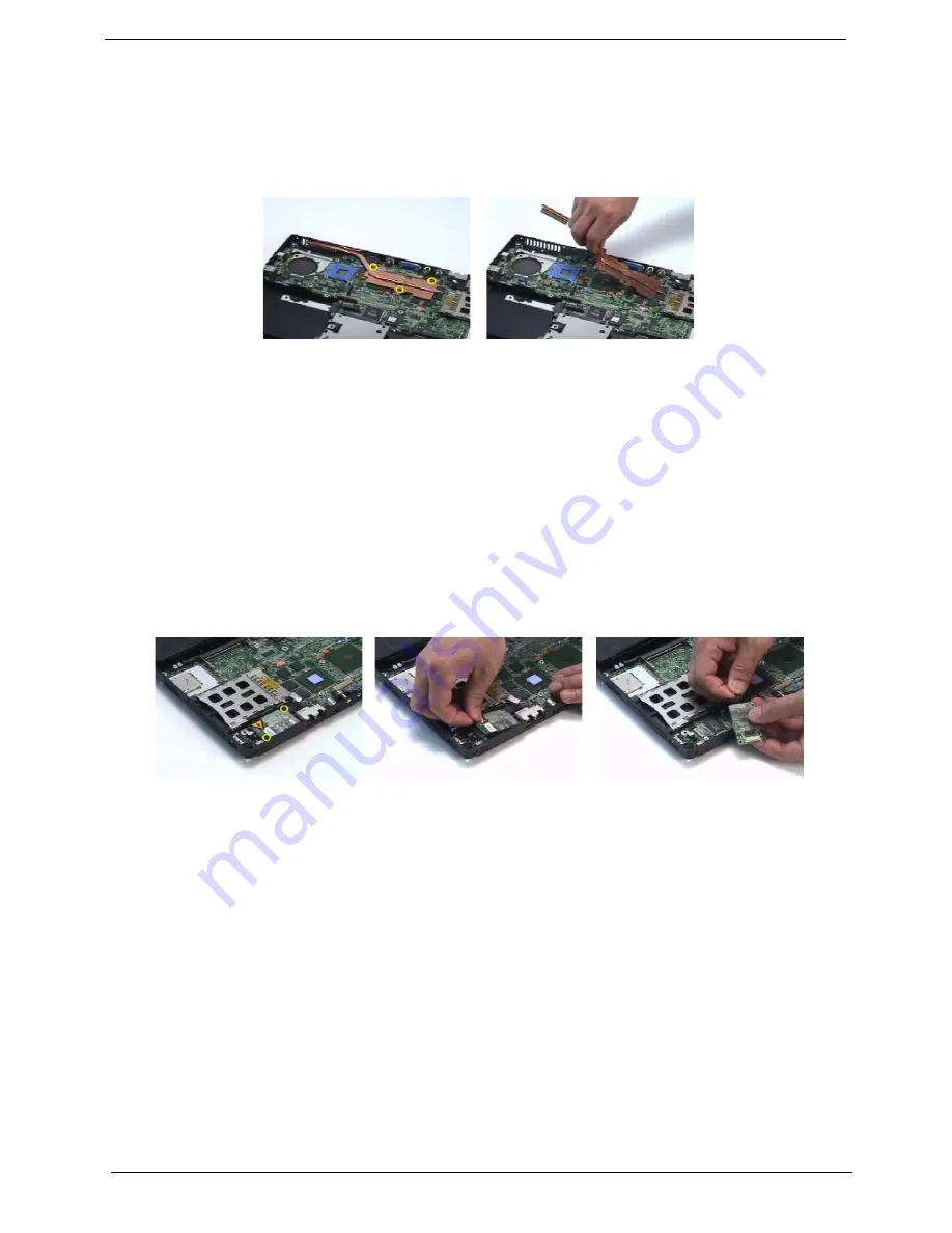
6.
Remove the three screws securing the VGA thermal module.
7.
Then detach the VGA thermal module.
Removing the Modem Board
1.
See “Removing the Battery” on page 56.
2.
See “Removing the Middle Cover” on page 60.
3.
See “Removing the Keyboard” on page 60.
4.
See “Removing the Power Board” on page 65.
5.
See “Removing the Upper Case Assembly” on page 65.
6.
Remove the two screws securing the modem board.
7.
Disconnect the modem board connector.
8.
Disconnect the modem board cable then remove the board.
Removing the Main Board
1.
See “Removing the Battery” on page 56.
2.
See “Removing the Middle Cover” on page 60.
3.
See “Removing the Keyboard” on page 60.
4.
See “Removing the Power Board” on page 65.
5.
See “Removing the Upper Case Assembly” on page 65.
6.
See “Removing the Speaker Set” on page 67.
7.
See “Removing the SW DJ Board Assembly” on page 67.
8.
See “Removing the Audio Board” on page 68.
9.
See “Removing the VGA Thermal Module” on page 68.
10.
See “Removing the Modem Board” on page 69.
11.
Remove the two nut screws securing the main board.
12.
Press the PCMCIA card button.
Содержание TRAVELMATE TravelMate 4080
Страница 8: ...Chapter 1 3 System Block Diagram ...
Страница 9: ...4 TravelMate 4070 4080 Board Layout Top View ...
Страница 56: ...51 Chapter 2 ...
Страница 61: ...Chapter 3 56 Removing the Battery 1 Unlatch the battery latch then remove the battery ...
Страница 69: ...Chapter 3 64 ...
Страница 76: ...71 Chapter 3 ...
Страница 95: ...Chapter 5 90 Top View Jumper and Connector Locations Chapter 5 ...
Страница 98: ...93 Chapter 5 ...
Страница 113: ...Chapter 6 108 ...