


Chapter 2
53
Main Menu
T
System Time and System Date:
The hours are displayed with 24-hour format. The changes in these two items take effect
immediately.
T
System Memory:
This item reports the memory size of system base memory. The size is fixed to 640KB.
T
Extended Memory:
It reports the memory size of the extended memory in the system. The extended memory size
is equal to total memory size (one MB).
T
Video Memory:
It indicates the video memory size.
T
Quiet Boot:
•
Enabled: Customer Logo is displayed, and Summary Screen is disabled.
•
Disabled: Customer Logo is displayed, and Summary Screen is enabled.
T
Power on Display:
•
Auto: During power on process, the system will detect if any display device is connected on
external video port. If any external display device is connected, the power on display will be
only in CRT (or projector) mode. Otherwise, it will be in LCD mode.
•
Both: Both the integrated LCD and the external video port (for an external CRT or projector)
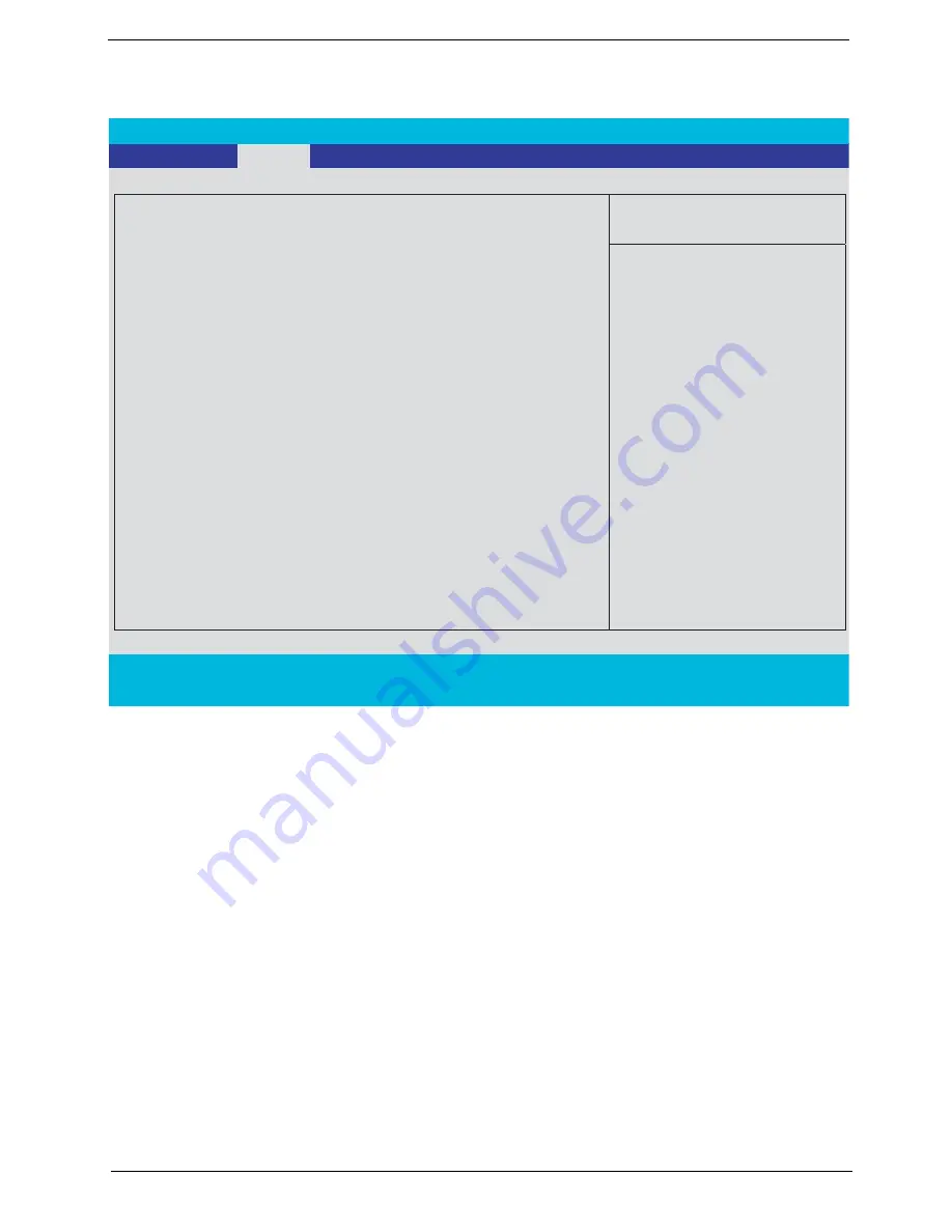
PhoenixBIOS Setup Utility
Info.
Main
Advanced Security Boot Exit
Item Specific Help
System Time:
[14:13:43]
System Date:
System Memory:
640 KB
Extended Memory:
1022 MB
Video Memory
256 MB
Quiet Boot:
[Enabled]
Power On Display:
[Both]
Network Boot
[Enabled]
F12 Boot Menu:
[Disabled]
<Tab>, <Shift-Tab>, or
<Enter> selects field.
F1
Help
↑ ↓
Select Item
F5/F6
Change Values
F9
Setup Defaults
Esc
Exit
←
→
Select Menu
Enter
Select
4
Sub -Menu
F10
Save and Exit
D2D Recovery:
Processor Power Management:
[Enabled]
[11/25/2005]
[Enabled]
Содержание TravelMate 8200
Страница 2: ...II PRINTED IN TAIWAN ...
Страница 30: ...20 Chapter 1 ...
Страница 35: ...Chapter 1 25 ...
Страница 37: ...Chapter 1 27 View information about Acer ePower Management ...
Страница 107: ...Chapter 4 97 8 You will see the screen displaying PASS when the system has built NAPP Master hard disk drive ...
Страница 108: ...Chapter 5 98 Top View of Main Board Jumper and Connector Locations Chapter 5 ...
Страница 109: ...99 Chapter 5 Part One of Top View Part Two of Top View ...
Страница 111: ...101 Chapter 5 Bottom View Part One of Bottom View ...
Страница 113: ...103 Chapter 5 CN12 PCMCIA card header SW03 Slider switch CN14 Five in one card reader Item Description Item Description ...
Страница 115: ...105 Chapter 6 Exploded Diagram ...


