Chapter 6
91
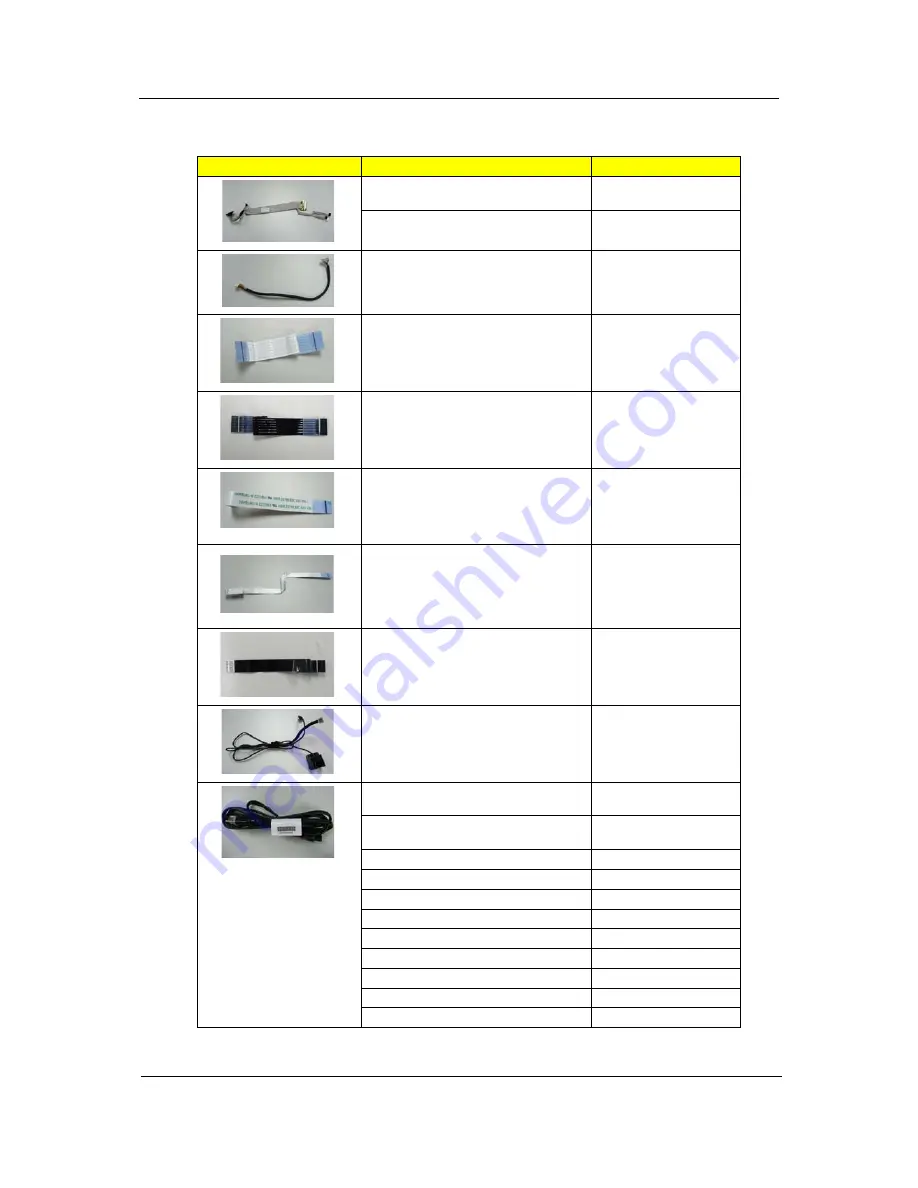
Cable
Category
Part Name and Description
Acer Part No.
LED LCD/CAMERA CABLE
50.TQP0N.006
LCD/CAMERA CABLE
50.TQP0N.008
BLUETOOTH BOARD CABLE
50.TQP0N.007
POWER BUTTON BOARD CABLE
50.TQP0N.001
HOTKEY BOARD CABLE
50.TQP0N.002
TOUCHPAD CABLE
50.TQP0N.004
TOUCAPAD BUTTON BOARD CABLE
50.TQP0N.003
3G SIMM BOARD CABLE
50.TQK0N.001
MODEM CABLE WITH RJ11
CONNECTOR
50.TQP0N.005
CORD-ROUND-3POS-1828mm-E-
POWER-USA
27.AAMVN.001
CORD-ROUND-3POS-1850mm-E-
POWER-EUR
27.AAMVN.002
POWER CORD 3PIN SOUTH AFRICA
27.AAMVN.008
POWER CORD 3PIN DENMARK
27.AAMVN.010
POWER CORD ISRAEL
27.AAMVN.011
POWER CORD 3PIN ITALIAN
27.AAMVN.009
POWER CORD 3PIN UK
27.AAMVN.004
POWER CORD 3PIN SWISS
27.AAMVN.006
POWER CORD AUSTRALIA W/LABEL
27.AAMVN.003
POWER CORD 3PIN CHINA
27.AAMVN.005
POWER CORD SOUTH AFRICA (AIL)
27.AAMVN.007
Содержание TravelMate 6293
Страница 6: ...VI ...
Страница 12: ...4 Chapter 1 System Block Diagram ...
Страница 46: ...38 Chapter 2 3 Execute SWin Flash Application 4 Select new BIOS update 5 Run Flash BIOS ...
Страница 49: ...Chapter 2 41 5 Press 確定 6 Press Start 7 Press 確定 8 Wait the disk format complete ...
Страница 50: ...42 Chapter 2 9 Press 確定 10 Press 關閉 11 Wait for the system to create the disk 12 Press 確定 when it s completed ...
Страница 51: ...Chapter 2 43 13 Press 否 14 nsert Floppy with the Crisis disk on system ...
Страница 54: ...46 Chapter 2 3 Rename it to bios wph ...
Страница 58: ...50 Chapter 3 LCM module disassembly flow chart ...
Страница 59: ...Chapter 3 51 Removing the Battery Pack 1 Release the battery 2 Slide the battery latch then remove the battery ...
Страница 68: ...60 Chapter 3 23 Disconnect Touchpad FFC 24 Disconnect BT cable ...
Страница 71: ...Chapter 3 63 Remove Main board 32 Remove M B from the BTCB ...
Страница 74: ...66 Chapter 3 Remove CCD cable 9 Disconnect CCD cable Remove LCD panel 10 Remove LCD panel from the TPDL ...
Страница 92: ...84 Chapter 4 ...
Страница 96: ...88 Chapter 6 TravelMate 6293 Exploded Diagram ...
Страница 108: ...100 Chapter 6 ...


