background image

Chapter 3

59

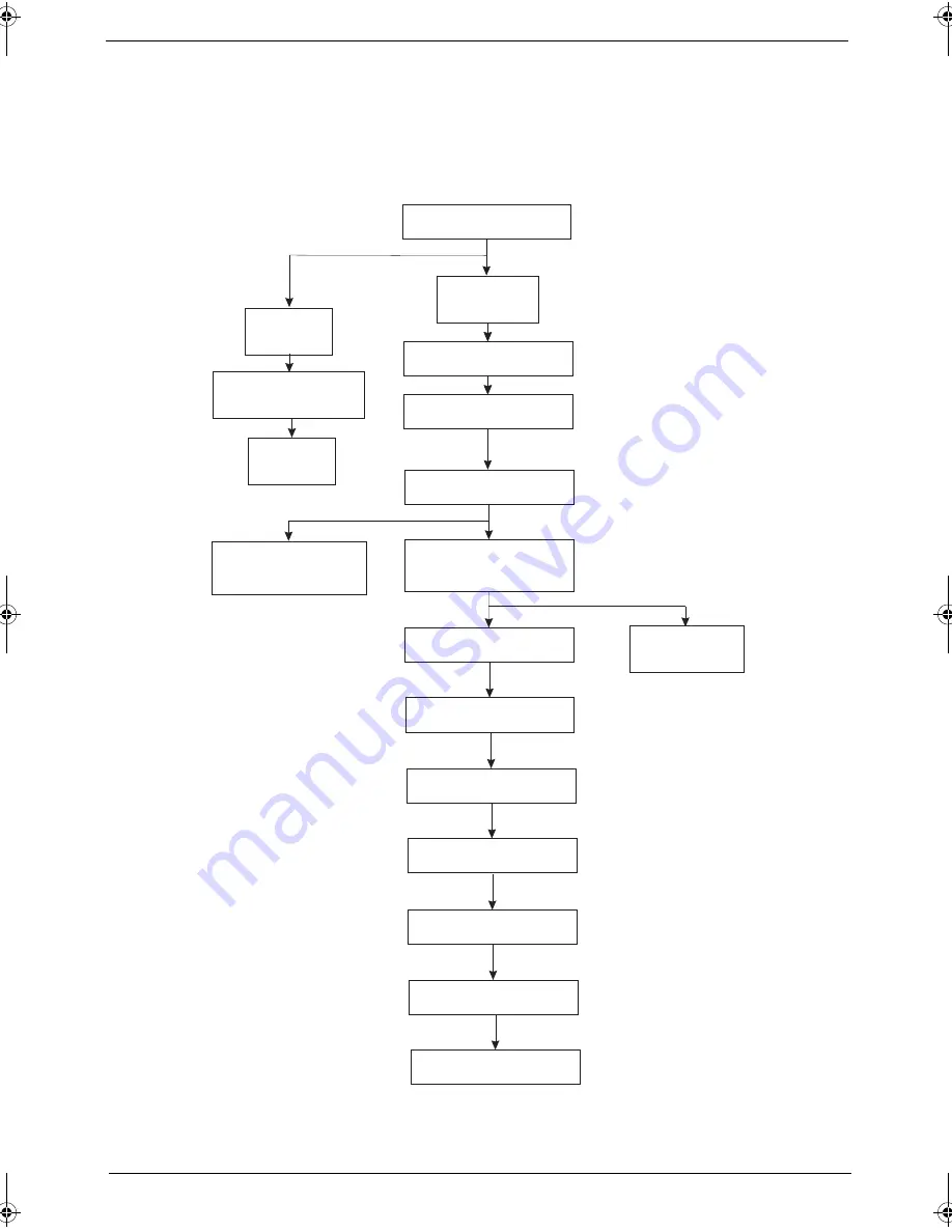
Main Unit Disassembly Process

Main Unit Disassembly Flowchart

MAIN

UNIT

KEYBOARD

MAIN UNIT DISASSEMBLY

MIDDLE

COVER

LCD MODULE

Dx4

UPPER CASE

Ax1, Gx11

TOUCHPAD BRACKET

ASSEMBLY

Cx4

CPU HEATSINK

MODULE

Fx2

FAN

Hx1

FINGERPRINT

BOARD

TOUCHPAD BOARD

Ax5

CPU

Cx2

LED INDICATORS

BOARD

Cx2

Cx2

DAUGHTER BOARD

Ax1

MAIN BOARD

Cx2

MODEM BOARD

BLUETOOTH BOARD

Ax2

SPEAKER MODULES

LOWER CASE

SG_TM4720_4320_Book.book  Page 59  Friday, April 20, 2007  11:14 AM

Содержание TravelMate 4720 Series

Страница 1: ...Acer Travelmate 4720 4320 Service Guide PRINTED IN TAIWAN Service guide files and updates are available on the ACER CSD web for more information please refer to http csd acer com tw ...

Страница 2: ...ii Revision History Please refer to the table below for the updates made on Travelmate 4720 4320 service guide Date Chapter Updates ...

Страница 3: ...ublication may be reproduced transmitted transcribed stored in a retrieval system or translated into any language or computer language in any form or by any means electronic mechanical magnetic optical chemical manual or otherwise without the prior written permission of Acer Incorporated ...

Страница 4: ... sold or licensed as is Should the programs prove defective following their purchase the buyer and not Acer Incorporated its distributor or its dealer assumes the entire cost of all necessary servicing repair and any incidental or consequential damages resulting from any defect in the software Acer is a registered trademark of Acer Corporation Intel is a registered trademark of Intel Corporation C...

Страница 5: ... bits and pieces of additional information related to the current topic WARNING Alerts you to any damage that might result from doing or not doing specific actions CAUTION Gives precautionary measures to avoid possible hardware or software problems IMPORTANT Reminds you to do specific actions relevant to the accomplishment of procedures ...

Страница 6: ...l NOT be covered in this generic service guide In such cases please contact your regional offices or the responsible personnel channel to provide you with further technical details 2 Please note WHEN ORDERING FRU PARTS that you should check the most up to date information available on your regional web or channel If for whatever reason a part number change is made it will not be noted in the print...

Страница 7: ...r Management 20 Acer ePresentation Management 22 Acer eDataSecurity Management 23 Acer eLock Management 24 Acer eRecovery Management 25 Acer eSettings Management 26 Windows Mobility Center 27 Using the System Utilities 28 Acer BiopProtect for selected models 28 Acer GridVista dual display compatible 29 Launch Manager 30 Norton Internet Security 30 NTI Shadow 31 Hardware Specifications and Configur...

Страница 8: ...pper Case from the Lower Case 70 Removing the Touchpad Board Module 71 Removing the Fingerprint Board 73 Removing the LED Indicators Board 74 Remove the Daughter Board 75 Removing the Mainboard 77 Removing the Modem Board 78 Removing the Bluetooth Board 79 Removing the Speaker Modules 80 LCD Module Disassembly Process 82 LCD Module Disassembly Flowchart 82 Removing the LCD Bezel 83 Removing the In...

Страница 9: ...nd Bottom View 112 Chapter 6 FRU Field Replaceable Unit List 117 Travelmate 4720 4320 Exploded Diagram 118 Travelmate 4720 4320 130 Appendix A Model Definition and Configuration 130 Appendix B Test Compatible Components 133 Microsoft Windows Vista Environment Test 134 Appendix C Online Support Information 135 ...

Страница 10: ...x ...

Страница 11: ... of dedicated system memory up to 256MB of shared system memory supporting Microsoft DirectX 9 and DirectX 10 K Dual independent display support K 16 7 million colors K MPEG 2 DVD hardware assisted capability K S video TV out NTSC PAL support Storage Subsystem K 80 120 160 GB or larger hard disk drive with Acer DASP Disk Anti Shock Protection enhancement K Optical drive options j DVD Super Multi d...

Страница 12: ...plify wireless technology or Intel PRO Wireless 3945ABG dual band tri mode 802 11a b g Wi Fi CERTIFIED network connection supporting Acer SignalUp wireless technology K WPAN Bluetooth 2 0 EDR Enhanced Data Rate K LAN Gigabit Ethernet Wake on LAN ready K Modem 56K ITU V 92 with PTT approval Wake on Ring ready I O Interface K PC Card slot one Type II K 5 in 1 card reader MS MS PRO MMC SD xD K Four U...

Страница 13: ...x 248 D x 29 7 41 08 H mm 13 03 x 9 76 x 1 17 1 62 inches 2 4 kg 5 29 lbs with 6 cell battery pack Environment K Temperature j Operating 5 C to 35 C j Non operating 20 C to 65 C K Humidity non condensing j operating 20 80 j Non operating 20 80 ...

Страница 14: ... Touch sensitive pointing device which functions like a computer mouse 8 Click buttons left center and right The left and right buttons function like the left and right mouse buttons The center button serves as a 4 way scroll button for selected models or Acer BioProtect fingerprint reader supporting Acer FingerNav 4 way control function for selected models 9 Status indicators Light Emitting Diode...

Страница 15: ... 0 devices e g USB mouse USB camera 5 Line in jack Accepts audio line in devices e g audio CD player stereo walkman mp3 player 6 Microphone jack Accepts inputs from external microphones 7 Headphones speaker line out jack Connects to audio line out devices e g speakers headphones 8 Bluetooth communication switch Enable disable the Bluetooth function manufacturing option 9 Wireless communication swi...

Страница 16: ...e USB camera 7 5 in 1 card reader Accepts Secure Digital SD MultiMediaCard MMC Memory Stick MS Memory Stick Pro MS PRO and xD Picture Card Note Only one card can operate at any given time Icon Item Description 1 PC Card slot eject button Ejects the PC Card from the slot 2 PC Card slot Accepts one Type II PC Card 3 Two USB 2 0 ports Connect to USB 2 0 devices e g USB mouse USB camera 4 S Video TV o...

Страница 17: ...m RJ 11 port Connects to a phone line Item Description 1 Battery bay Houses the computer s battery pack 2 Battery lock Locks the battery in position 3 Hard disk bay Houses the computer s hard disk secured with screws 4 Memory compartment Houses the computer s main memory 5 Battery release latch Releases the battery to remove the battery pack ...

Страница 18: ...ing complete Icon Function Description HDD Indicates when the hard disc or optical drive is active Num lock Lights when Num Lock is activated Cap lock Lights when Cap Lock is activated Power Lights up when the computer is on Battery Lights up when the battery is being charged Bluetooth Indicates the status of Bluetooth communication Wireless LAN Indicates the status of wireless LAN communication I...

Страница 19: ... Internet programs but can be reset by users To set the Web browser mail and programmable buttons run the Acer Launch Manager Icon Easy launch button Default application Acer Empowering Technology Acer Empowering Technology User programmable Mail Email application user programmable Web browser Internet browser user programmable P Programmable key User programmable Acer Empowering Technology on pag...

Страница 20: ...m when you need to leave your desk K Presentation key prepares your system display for presentation a handy shortcut for busy professionals K Sync key synchronizes your system to an externally attached storage device for convenient backup Icon Easy launch button Default application Lock Launch Windows Lock function Presentation Minimizes your open windows and prepares your display for presenting S...

Страница 21: ...Tapping on the touchpad is the same as clicking the left button K Use the 4 way scroll 3 button for selected models or Acer BioProtect fingerprint reader 3 supporting Acer FingerNav 4 way control function for selected models to scroll up or down and move left or right a page This button or fingerprint reader mimics your cursor pressing on the right scroll bar of Windows applications Function Left ...

Страница 22: ...e response Tapping too hard will not increase the touchpad s responsiveness NOTE By default vertical and horizontal scrolling is enabled on your touchpad It can be disabled under Mouse settings in Windows Control Panel Access context menu Click once Scroll Click and hold to move up down left right Function Left Button 1 Right Button 4 Main touchpad 2 Center button 3 ...

Страница 23: ...are in uppercase Num Lock Fn F11 When Num Lock is on the embedded keypad is in numeric mode The keys function as a calculator complete with the arithmetic operators and Use this mode when you need to do a lot of numeric data entry A better solution would be to connect an external keypad Scroll Lock Fn F12 When Scroll Lock is on the screen moves one line up or down when you press the up or down arr...

Страница 24: ...work domain M Minimizes all windows R Open the Run dialog box T Cycle through programs on the taskbar U Open Ease of Access Center X Open Windows Mobility Center BREAK Display the System Properties dialog box SHIFT M Restore minimized windows to the desktop TAB Cycle through programs on the taskbar by using Windows Flip 3 D SPACEBAR Bring all gadgets to the front and select Windows Sidebar CTRL F ...

Страница 25: ...r ePower Management Launches the Acer ePowerManagement in Acer eManager Fn F4 Sleep Puts the computer in Sleep mode Fn F5 Display toggle Switches display output between the display screen external monitor if connected and both Fn F6 Screen blank Turns the display screen backlight off to save power Press any key to return Fn F7 Touchpad toggle Turns the internal touchpad on and off Fn F8 Speaker to...

Страница 26: ...Alt Gr and then press the 5 key at the upper center of the keyboard NOTE Some fonts and software do not support the Euro symbol Please refer to www microsoft com typography faq faq12 htm for more information The US dollar sign 1 Open a text editor or word processor 2 Either press at the bottom right of the keyboard or hold Shift and then press the 4 key at the upper center of the keyboard NOTE Thi...

Страница 27: ...ia K Acer eRecovery Management backs up and recovers data flexibly reliably and completely K Acer eSettings Management accesses system information and adjusts settings easily For more information right click on the Empowering Technology toolbar then select the Help or Tutorial function Empowering Technology Password Before using Acer eLock Management and Acer eRecovery Management you must initiali...

Страница 28: ...t Management from the Empowering Technology toolbar or run the program from the Acer Empowering Technology program group in Start menu You can also set Acer eNet Management to start automatically when you boot up your PC Acer eNet Management automatically detects the best settings for a new location while offering you the option to manually adjust the settings to match your needs ...

Страница 29: ...h to the appropriate profile when you move from one location to another Settings stored include network connection settings IP and DNS settings wireless AP details etc as well as default printer settings Security and safety concerns mean that Acer eNet Management does not store username and password information ...

Страница 30: ...r plans To create a new power plan Creating customized power plans allows you to save and quickly switch to a personalized set of power options 1 Click the Create Power Plan icon 2 Enter a name for your new power plan 3 Choose a predefined power plan to base your customized plan on 4 If necessary change the display and sleep settings you want your computer to use 5 Click OK to save your new power ...

Страница 31: ...pter 1 21 Battery status For real time battery life estimates based on current usage refer to the panel in the upper half of the window Click the to view estimated battery life in sleep and hibernate modes ...

Страница 32: ...be automatically switched out when an external display is connected to the system For projectors and external devices that are not auto detected launch Acer ePresentation Management to choose an appropriate display setting NOTE If the restored resolution is not correct after disconnecting a projector or you need to use an external resolution that is not supported by Acer ePresentation Management a...

Страница 33: ...The Acer eDataSecurity Management setup wizard will prompt you for a supervisor password and default encryption password This password will be used to encrypt files by default or you can choose to enter your own password when encrypting a file NOTE The password used to encrypt a file is the unique key that the system needs to decrypt it If you lose the password the supervisor password is the only ...

Страница 34: ...hat can be mounted as a file system when plugged into the system K Optical Drive Devices includes any kind of CD ROM DVD ROM HD DVD or Blu ray drive devices K Floppy Drive Devices 3 5 inch floppy drives only To use Acer eLock Management the Empowering Technology password must be set first Once set you can apply locks to any of the devices types Lock s will immediately be set without any reboot nec...

Страница 35: ...ps to hard disk or optical disc K Creation of backups j Factory default image j User backup image j Current system configuration j Application backup K Restore and recovery j Factory default image j User backup image j From previously created CD DVD j Reinstall applications drivers NOTE If your computer did not come with a Recovery CD or System CD please use Acer eRecovery Management s System back...

Страница 36: ...allows you to inspect hardware specifications set BIOS passwords and modify boot options Acer eSettings Management also K Provides a simple graphical user interface for navigation K Prints and saves hardware specifications K Lets you set an asset tag for your system ...

Страница 37: ...eless networking on off external display settings display orientation and synchronization status Windows Mobility Center also includes Acer specific settings like Bluetooth Add Device if applicable sharing folders overview sharing service on or off and a shortcut to the Acer user guide drivers and utilities To launch Windows Mobility Center K Use the shortcut key X K Start Windows Mobility Center ...

Страница 38: ...s to your computer with Pre Boot Authentication PBA centralized password management with Password Bank and fast application website launching and login with Acer FingerLaunch Acer BioProtect Fingerprint Solution also allows you to navigate through web browsers and documents using Acer FingerNav With Acer BioProtect Fingerprint Solution you can now enjoy an extra layer of protection for your person...

Страница 39: ...y settings so you can view multiple windows on the same screen To access this function please go to Start All Programs and click on Acer GridVista You may choose any one of the four display settings indicated below Double vertical Triple primary at left Triple primary at right or Quad Acer Gridvista is dual display compatible allowing two displays to be partitioned independently Acer GridVista is ...

Страница 40: ...uses 1 Double click the Norton Internet Security icon on the Windows desktop 2 Select Tasks Scans 3 Select Run Scan to scan your system 4 When the scan is complete review the results of the scan NOTE For optimal security run a Full System Scan when scanning your computer for the first time You can schedule customized virus scans that run unattended on specific dates and times or at periodic interv...

Страница 41: ... time or whenever any data in the backup source are modified Shadow can also be configured to archive file versions If this option is enabled then any file that is saved or overwritten will trigger Shadow to archive the previous version of the file The file versions are stored in a Revisions folder in the backup destination Users can configure how many versions of a file to maintain Shadow support...

Страница 42: ...ress chipset Audio controller Codec ALC268 PCMCIA controller TI7412 LAN controller Intel ICH8M Broadcom 5785KMLG chipsets Modem controller Intel ICH8M chipset Keyboard controller Winbond WPC8768L Hard Disk Drive Interface Item Specification Product Hitachi Travelstar 5K160 Toshiba Western Digital Model Name HGST HTS541612 J9SA00 HGST HTS541616 J9SA00 MK1237GS X MK1637GS X WD1200BE VS WD1600BE VS F...

Страница 43: ... AHCI support iAMT 2 5 System Memory Item Specification Memory controller Intel GM965 Express chipset DIMM socket number 2 sockets Supports maximum memory size 2 GB for 32 bit OS 4 GB for 64bit OS Supports DIMM type DDR2 Synchronous DRAM Supports DIMM Speed 533 677 MHz Video Item Specification VGA controller Intel GM965 Express chipset with integrated 3D graphics Features Intel Graphic Media Accel...

Страница 44: ...ler Intel ICH8M chipset Vendor Agere Baud rate 56 K Modem connector type RJ11 Bluetooth Module Item Specification Vendor Foxconn Model name T60H928 01 Protocol Bluetooth 2 0 Connector type Mini USB Keyboard and Input Devices Item Specification Keyboard controller Winbond WPC8768L Model name Acer FineTouch keyboard Features 5 degree curve 88 89 key inverted T cursor layout 2 5 mm minimum key travel...

Страница 45: ...ply 5 V DC DVD Drive Interface Item Specification Vendor Sony Pioneer HLDS Model name AD 7530A DVR K17RS GSA T10N Drive type Internal Slim DVD CD writer Data transfer rate Write CD R 24X CAV CD RW 24X CAV DVD R R RW RW single layer 6X 8X ZCLV DVD R R double layer 8X CAV DVD RAM 5X ZCLV Read CD R RW ROM 24X Max DVD ROM single layer 8X DVD ROM double layer 6X DVD RAM 5X ZCLV DVD R R RW RW single lay...

Страница 46: ...I1 L03 Glare Screen diagonal mm 14 1 WXGA 14 1 WXGA 14 1 WXGA Display resolution pixels 1280 x 800 1280 x 768 1280 x 800 Aspect ratio 16 10 15 9 N A Active area mm 303 36 x 189 6 305 8 x 183 2 N A Pixel pitch mm 0 237 0 2385 107 N A Mode TN N A N A Number of colors 262 K 262 144 6 bit 262 K Color saturation NTSC 45 45 N A Typical white luminance cd m2 also called brightness 200 185 typ 5p 220 Cont...

Страница 47: ...he system are turned off completely Soft Off G2 S5 OS initiated shutdown All devices in the system are turned off completely On Working G0 S0 Individual devices such as the CPU and hard disc may be power managed in this state Suspend to RAM S3 CPU set power down VGA Suspend PCMCIA Suspend Audio Power Down Hard Disk Power Down CD ROM Power Down and Super I O Low Power mode Save to Disk S4 Also call...

Страница 48: ...38 Chapter 1 ...

Страница 49: ...g each of the screen illustrations settings in boldface are the default and suggested parameter settings BIOS Setup Navigation Keys Note the following reminders when moving around the Setup utility K Use the Left and Right arrow keys to move to the next page or to return to the previous screen K Use the Up and Down arrow keys to select an item K Use the and keys to select an option NOTE You can co...

Страница 50: ...number of the VGA firmware KBC Version Version number of the keyboard controller Serial Number Serial number of the system Asset Tag Number Asset tag number of the system Product Name Product name of the system Manufacturer Name Name of the manufacturer of this system UUID Visible only when an internal LAN device is present UUID 32bytes Phoenix TrustedCore tm Setup Utility Main CPU Type CPU Speed ...

Страница 51: ...r LAN such as a remote server Option Enabled or Disabled F12 Boot Menu When Enabled pressing the F12 key during POST brings up a menu of devices that you can select to boot Option Disabled or Enabled D2D Recovery Enables or disables disk to disk recovery D2D recovery is a method of restoring the system to factory configurations without using recovery CDs Option Enabled or Disabled Phoenix TrustedC...

Страница 52: ...abled or Disabled Infrared Port Enables or disables the infrared port Option Enabled or Disabled ASF Configuration Press Enter to configure the Alert Standard Format feature Phoenix TrustedCore tm Setup Utility Main Item Specific Help Configure AHCI Mode using options Disabled No configuration Enabled User configuration AHCI Mode Infrared Port ASF Configuration F1 Esc Help Exit Select Item Select ...

Страница 53: ...Enter to configure the user password Set Secondary MAS Disk Password Press Enter to configure the hard disc drive password Password on Boot Enables or disables security check during POST Disabled or Enabled Phoenix TrustedCore tm Setup Utility Main Item Specific Help Supervisor Password controls access of the whole setup utility It can be used to boot up when Password on boot is enabled Supervisor...

Страница 54: ...sword parameter Set Supervisor Password Set User Password or Set Secondary MAS Disk Password then press Enter 2 Type the original password then press Enter 3 Type a new password then press Enter 4 Retype the password to verify the first entry then press Enter again 5 Press F10 6 Select Yes to save the new password and close the Setup Utility Removing a System Password 1 Use the up down keys to sel...

Страница 55: ...cified is not bootable Phoenix TrustedCore tm Setup Utility Main Item Specific Help Use or to select a device then press F6 to move it up the list or F5 to move it down the list Press Esc to escape the menu Boot priority order F1 Esc Help Exit Select Item Select Menu Change Values Select Sub Menu Enter F9 F10 Setup Defaults Save and Exit Information Advanced Security Boot Exit 2 IDE1 3 CD DVD XXXX...

Страница 56: ...inds of low performance components and you choose to load these settings the system might not function properly Discard Changes Discards all changes made in the BIOS setup Save Changes Saves changes made in the BIOS setup Phoenix TrustedCore tm Setup Utility Main Item Specific Help Exit System Setup and save your changes to CMOS F1 Esc Help Exit Select Item Select Menu Change Values Select Sub Men...

Страница 57: ...K Wrist grounding strap and conductive mat for preventing electrostatic discharge K Flat screwdriver K Philips screwdriver K Hex screwdriver K Plastic flat screwdriver K Plastic tweezers NOTE The screws for the different components vary in size During the disassembly process group the screws with the corresponding components to avoid mismatch when putting back the components Chapter 3 Machine Disa...

Страница 58: ...sassembly procedure make sure that you do the following 1 Turn off the power to the system and all peripherals 2 Unplug the AC adapter and all power and signal cables from the system 3 Place the system on a flat stable surface 4 Remove the battery pack See Removing the Battery Pack on page 51 ...

Страница 59: ...mponents For example if you want to remove the mainboard you must first remove the keyboard then disassemble the inside assembly frame in that order Main Screw List Item Screw Color Part No A M2 x L4 Black and Silver 86 9A552 4R0 B M2 x L18 Black 86 00G64 720 C M2 x L3 Silver 86 9A552 3R0 D M3 x L4 Silver 86 9A524 4R0 E M2 5 x L6 Black 86 00E33 736 F M2 x L2 5 Silver 86 00F22 722 G M2 x L3 Silver ...

Страница 60: ...e the keyboard then disassemble the inside assembly frame in that order Screw List Screw Part No A M2 x L4 86 9A552 4R0 B M2 x L18 86 00G64 720 C M2 x L3 86 9A552 3R0 D M3 x L4 86 9A524 4R0 E M2 5 x L6 86 00E33 736 F M2 x L2 5 86 00F22 722 TURN OFF POWER AND PERIPHERALS UNPLUG POWER CABLES LOWER COVER Bx1 OPTICAL DISK DRIVE MODULE Ex1 OPTICAL DISK DRIVE OPTICAL LOCKER BRACKET HDD MODULE Fx1 Ax4 WL...

Страница 61: ...he unlock position 1 3 Slide and hold the battery release latch to the release position 2 then remove the battery from the main unit 3 Removing the SD Dummy Card 1 See Removing the Battery Pack on page 51 2 Push against the card as if you were pushing it further into the slot letting the card spring out ...

Страница 62: ... card from the slot Removing the Express Dummy Card 1 See Removing the Battery Pack on page 51 2 Push the eject button all the way in to release the button 3 Push it again to eject the dummy card 4 Remove the card from the slot ...

Страница 63: ...ew B on the lower cover 6 Use a plastic screw driver to pry open the lower cover 7 Remove the lower cover from the lower case Removing the DIMM 1 See Removing the Battery Pack on page 51 2 See Removing the SD Dummy Card on page 51 3 See Removing the Express Dummy Card on page 52 4 See Removing the Lower Cover on page 53 Step Size Quantity Color Torque 1 4 M2 x L4 4 Black 1 6 kgf cm Step Size Quant...

Страница 64: ...he DIMM module 7 Do the same on the other board Removing the WLAN Board Modules 1 See Removing the Battery Pack on page 51 2 See Removing the SD Dummy Card on page 51 3 See Removing the Express Dummy Card on page 52 4 See Removing the Lower Cover on page 53 5 Remove the mylar tape from the mic cable ...

Страница 65: ... board from the WLAN socket NOTE When attaching the antennas back to the WLAN board make sure the cable are routed properly Removing the Hard Disk Drive Module 1 See Removing the Battery Pack on page 51 2 See Removing the SD Dummy Card on page 51 3 See Removing the Express Dummy Card on page 52 4 See Removing the Lower Cover on page 53 Step Size Quantity Color Torque 1 2 M2 x L3 2 Silver 1 6 kgf c...

Страница 66: ... its bay NOTE To prevent damage to device avoid pressing down on it or placing heavy objects on top of it 6 Remove the HDD rubber enclosure by gently prying open the enclosure starting on either side 3 and proceeding down the bottom 4 and towards the top of the disk 5 then pull it up to detach from the HDD module 6 ...

Страница 67: ...ck on page 51 2 See Removing the SD Dummy Card on page 51 3 See Removing the Express Dummy Card on page 52 4 See Removing the Lower Cover on page 53 5 Turn the base unit over then remove the screw E on the bottom side of the unit Step Size Quantity Color Torque 7 M3 x L4 2 Silver 1 6 kgf cm Step Size Quantity Color Torque 1 M2 x L6 1 Black 1 6 kgf cm ...

Страница 68: ...he module forward then slide out the optical drive module from the main unit 7 Remove the two screws F securing the optical bracket and remove the locker bracket from the optical disk drive module Step Size Quantity Color Torque 1 2 M2 x L2 5 2 Silver 1 6 kgf cm ...

Страница 69: ...AIN UNIT DISASSEMBLY MIDDLE COVER LCD MODULE Dx4 UPPER CASE Ax1 Gx11 TOUCHPAD BRACKET ASSEMBLY Cx4 CPU HEATSINK MODULE Fx2 FAN Hx1 FINGERPRINT BOARD TOUCHPAD BOARD Ax5 CPU Cx2 LED INDICATORS BOARD Cx2 Cx2 DAUGHTER BOARD Ax1 MAIN BOARD Cx2 MODEM BOARD BLUETOOTH BOARD Ax2 SPEAKER MODULES LOWER CASE ...

Страница 70: ... Removing the Express Dummy Card on page 52 4 See Removing the Lower Cover on page 53 5 Detach the heatsink cable 6 Detach the tin foil tape on the fan Screw List Screw Part No A M2 x L4 86 00G64 720 C M2 x L3 Black 86 9A552 3R0 D M2 5 x L6 86 00E33 736 F M2 x L2 5 86 00F22 722 G M2 x L3 Silver 86 00C07 220 H M2 x L3 86 00C07 220 ...

Страница 71: ...ge 51 2 See Removing the SD Dummy Card on page 51 3 See Removing the Express Dummy Card on page 52 4 See Removing the Lower Cover on page 53 5 See Removing the Fan Module on page 60 6 Unfasten the screws A securing the heatsink in the order shown Step Size Quantity Color Torque 1 2 M2 x L2 5 2 Silver 1 6 kgf cm Step Size Quantity Color Torque 1 5 M2 x L4 5 Silver 1 6 kgf cm ...

Страница 72: ...atsink Removing the CPU 1 See Removing the Battery Pack on page 51 2 See Removing the SD Dummy Card on page 51 3 See Removing the Express Dummy Card on page 52 4 See Removing the Lower Cover on page 53 5 See Removing the Fan Module on page 60 6 See Removing the CPU Heatsink Module on page 61 ...

Страница 73: ...he corner as shown Removing the Middle Cover 1 See Removing the Battery Pack on page 51 2 See Removing the SD Dummy Card on page 51 3 See Removing the Express Dummy Card on page 52 4 See Removing the Lower Cover on page 53 5 See Removing the Fan Module on page 60 6 See Removing the CPU Heatsink Module on page 61 7 Open the LCD screen all the way to facilitate the easy removal of the middle cover ...

Страница 74: ... middle cover and gently pry up the middle cover 9 Continue prying the middle cover until the full length of the cover releases from the main unit then remove the cover Removing the Keyboard 1 See Removing the Battery Pack on page 51 2 See Removing the Middle Cover on page 63 ...

Страница 75: ...Chapter 3 65 3 Remove the two screws C securing the keyboard 4 Carefully pry up and out the keyboard and turn it over Step Size Quantity Color Torque 1 2 M2 x L3 2 Silver 1 6 kgf cm ...

Страница 76: ...66 Chapter 3 5 Disconnect the keyboard cable from the mainboard to remove the keyboard ...

Страница 77: ...ard on page 52 4 See Removing the Lower Cover on page 53 5 See Removing the Fan Module on page 60 6 See Removing the CPU Heatsink Module on page 61 7 See Removing the CPU on page 62 8 See Removing the Middle Cover on page 63 9 See Removing the Keyboard on page 64 10 Disconnect the LED cable 11 Disconnect the fingerprint cable 12 Disconnect the touchpad cable ...

Страница 78: ...68 Chapter 3 13 Disconnect the internal microphone cable 14 Detach the mylar tape securing the mic and antenna cables to the upper case 15 Carefully release the cables from the latches as shown ...

Страница 79: ... cable 17 Disconnect the LCD coaxial cable from the mainboard 18 Disconnect the cover switch cable from the mainboard 19 Turn the system over and remove the two screws D from the base of the unit Step Size Quantity Color Torque 1 2 M2 5 x L6 2 Black 3 0 kgf cm ...

Страница 80: ...emoving the Battery Pack on page 51 2 See Removing the SD Dummy Card on page 51 3 See Removing the Express Dummy Card on page 52 4 See Removing the Lower Cover on page 53 5 See Removing the Fan Module on page 60 6 See Removing the CPU Heatsink Module on page 61 7 See Removing the CPU on page 62 8 See Removing the Middle Cover on page 63 9 See Removing the Keyboard on page 64 10 See Removing the LC...

Страница 81: ... on page 51 2 See Removing the SD Dummy Card on page 51 3 See Removing the Express Dummy Card on page 52 4 See Removing the Lower Cover on page 53 5 See Removing the Fan Module on page 60 6 See Removing the CPU Heatsink Module on page 61 7 See Removing the CPU on page 62 8 See Removing the Middle Cover on page 63 Step Size Quantity Color Torque 1 M2 x L4 2 Black 1 6 kgf cm Step Size Quantity Color...

Страница 82: ... Case from the Lower Case on page 70 12 Disconnect the touchpad cable from the touchpad board 13 Disconnect the fingerprint cable from the fingerprint board 14 Remove the four screws C on the touchpad bracket 15 Detach the touchpad bracket from the upper case Step Size Quantity Color Torque 1 4 M2 x L3 4 Silver 1 6 kgf cm ...

Страница 83: ...moving the SD Dummy Card on page 51 3 See Removing the Express Dummy Card on page 52 4 See Removing the Lower Cover on page 53 5 See Removing the Fan Module on page 60 6 See Removing the CPU Heatsink Module on page 61 7 See Removing the CPU on page 62 8 See Removing the Middle Cover on page 63 9 See Removing the Keyboard on page 64 10 See Removing the LCD Module on page 67 11 See Separating the Up...

Страница 84: ...g the Express Dummy Card on page 52 4 See Removing the Lower Cover on page 53 5 See Removing the Fan Module on page 60 6 See Removing the CPU Heatsink Module on page 61 7 See Removing the CPU on page 62 8 See Removing the Middle Cover on page 63 9 See Removing the Keyboard on page 64 10 See Removing the LCD Module on page 67 11 See Separating the Upper Case from the Lower Case on page 70 Step Size...

Страница 85: ...ack on page 51 2 See Removing the SD Dummy Card on page 51 3 See Removing the Express Dummy Card on page 52 4 See Removing the Lower Cover on page 53 5 See Removing the Fan Module on page 60 6 See Removing the CPU Heatsink Module on page 61 7 See Removing the CPU on page 62 8 See Removing the Middle Cover on page 63 9 See Removing the Keyboard on page 64 10 See Removing the LCD Module on page 67 S...

Страница 86: ...12 Disconnect the Bluetooth board cable from the mainboard 13 Disconnect the speaker cable from the mainboard 14 Remove the two screws C that secures the daughter board to the mainboard 15 Detach the daughter board Step Size Quantity Color Torque 1 4 M2 x L3 2 Silver 1 6 kgf cm ...

Страница 87: ...moving the CPU Heatsink Module on page 61 7 See Removing the CPU on page 62 8 See Removing the Middle Cover on page 63 9 See Removing the Keyboard on page 64 10 See Removing the LCD Module on page 67 11 See Separating the Upper Case from the Lower Case on page 70 12 See Remove the Daughter Board on page 75 13 Remove the screw A holding the mainboard 14 Carefully detach the mainboard from the lower...

Страница 88: ...the Express Dummy Card on page 52 4 See Removing the Lower Cover on page 53 5 See Removing the Fan Module on page 60 6 See Removing the CPU Heatsink Module on page 61 7 See Removing the CPU on page 62 8 See Removing the Middle Cover on page 63 9 See Removing the Keyboard on page 64 10 See Removing the LCD Module on page 67 11 See Separating the Upper Case from the Lower Case on page 70 12 See Remo...

Страница 89: ...he Lower Cover on page 53 5 See Removing the Fan Module on page 60 6 See Removing the CPU Heatsink Module on page 61 7 See Removing the CPU on page 62 8 See Removing the Middle Cover on page 63 9 See Removing the Keyboard on page 64 10 See Removing the LCD Module on page 67 11 See Separating the Upper Case from the Lower Case on page 70 12 See Remove the Daughter Board on page 75 13 See Removing t...

Страница 90: ...oving the CPU Heatsink Module on page 61 7 See Removing the CPU on page 62 8 See Removing the Middle Cover on page 63 9 See Removing the Keyboard on page 64 10 See Removing the LCD Module on page 67 11 See Separating the Upper Case from the Lower Case on page 70 12 See Remove the Daughter Board on page 75 13 See Removing the Mainboard on page 77 14 See Removing the Bluetooth Board on page 79 15 Re...

Страница 91: ...Chapter 3 81 16 Carefully detach the speaker modules as shown ...

Страница 92: ...9A552 3R0 E M2 5 x L6 86 00E33 736 I M2 5 x L5 86 00F87 735 J M2 5 x L5 86 00F00 735 LCD MODULE LCD BEZEL LEFT HINGE RIGHT HINGE Ix4 Ex2 Ex1 Ex1 LCD ASSEMBLY LEFT LCD BRACKET Cx4 RIGHT LCD BRACKET Cx4 CCD BOARD INVERTER BOARD LCD BACK PANEL AUXILIARY ANTENNA MICROPHONE LCD MODULE DISASSEMBLY Ix2 Jx2 LCD FPC CABLE MAIN ANTENNA ...

Страница 93: ...dule on page 60 6 See Removing the CPU Heatsink Module on page 61 7 See Removing the CPU on page 62 8 See Removing the Middle Cover on page 63 9 See Removing the Keyboard on page 64 10 See Removing the LCD Module on page 67 11 Remove the six rounded screw caps as shown 12 Remove the six screws Ix4 Ex2 on the LCD module in the order as shown Step Size Quantity Color Torque 1 4 M2 5 x L5 4 Black 3 0...

Страница 94: ... 52 4 See Removing the Lower Cover on page 53 5 See Removing the Fan Module on page 60 6 See Removing the CPU Heatsink Module on page 61 7 See Removing the CPU on page 62 8 See Removing the Middle Cover on page 63 9 See Removing the Keyboard on page 64 10 See Removing the LCD Module on page 67 11 See Removing the LCD Bezel on page 83 12 Remove the screw I that hold the board to the panel Step Size...

Страница 95: ... Pack on page 51 2 See Removing the SD Dummy Card on page 51 3 See Removing the Express Dummy Card on page 52 4 See Removing the Lower Cover on page 53 5 See Removing the Fan Module on page 60 6 See Removing the CPU Heatsink Module on page 61 7 See Removing the CPU on page 62 8 See Removing the Middle Cover on page 63 9 See Removing the Keyboard on page 64 10 See Removing the LCD Module on page 67...

Страница 96: ... CCD board then remove the board 14 Remove the two screws J securing the left and right LCD brackets 15 Carefully detach the cables from the latches on the LCD bracket as shown 16 Detach the LCD with the brackets from the back cover Step Size Quantity Color Torque 1 2 M2 5 x L5 2 Silver 2 5 kgf cm ...

Страница 97: ... the SD Dummy Card on page 51 3 See Removing the Express Dummy Card on page 52 4 See Removing the Lower Cover on page 53 5 See Removing the Fan Module on page 60 6 See Removing the CPU Heatsink Module on page 61 7 See Removing the CPU on page 62 8 See Removing the Middle Cover on page 63 9 See Removing the Keyboard on page 64 10 See Removing the LCD Module on page 67 11 See Removing the LCD Bezel ...

Страница 98: ...88 Chapter 3 14 Remove the eight screws C securing the left and right LCD brackets to remove the brackets Step Size Quantity Color Torque 1 8 M2 x L3 8 Silver 1 6 kgf cm ...

Страница 99: ...oving the CPU on page 62 8 See Removing the Middle Cover on page 63 9 See Removing the Keyboard on page 64 10 See Removing the LCD Module on page 67 11 See Removing the LCD Bezel on page 83 12 See Removing the Inverter Board on page 84 13 See Removing the LCD with Brackets on page 85 14 See Removing the LCD Brackets on page 87 15 Remove the two screws E securing the left and right LCD module hinge...

Страница 100: ...the CPU on page 62 8 See Removing the Middle Cover on page 63 9 See Removing the Keyboard on page 64 10 See Removing the LCD Module on page 67 11 See Removing the LCD Bezel on page 83 12 See Removing the Inverter Board on page 84 13 See Removing the LCD with Brackets on page 85 14 Detach the gasket tape holding the right antenna in place remove the antenna bracket then carefully remove the antenna...

Страница 101: ...e CPU Heatsink Module on page 61 7 See Removing the CPU on page 62 8 See Removing the Middle Cover on page 63 9 See Removing the Keyboard on page 64 10 See Removing the LCD Module on page 67 11 See Removing the LCD Bezel on page 83 12 See Removing the Inverter Board on page 84 13 See Removing the LCD with Brackets on page 85 14 See Removing the Antennas on page 90 15 Carefully remove the microphon...

Страница 102: ...92 Chapter 3 ...

Страница 103: ...possible 2 Verify the symptoms by attempting to recreate the failure by running the diagnostic tests or repeating the same operation 3 Do not use any power sources when performing an assembly or disassembly procedures 4 If any problems occur you can perform the following visual inspection before you continue K Power cords are properly connected and secured K There are no obvious shorts or opens K ...

Страница 104: ... the internal keyboard does not work or an unexpected error occurs make sure that the flexible cable extending from the internal keyboard is correctly connected to the mainboard If the keyboard cable connection is correct run the Keyboard Test If the tests detect a keyboard problem do the following procedures in sequence to correct the problems Do not replace a non defective FRU 1 Reconnect the ke...

Страница 105: ...always indicate a defect 3 If the power on indicator does not light up check if the adapter s power cord is properly connected to the system 4 If the operational charge does not work see Check the Battery Pack on page 95 Check the Battery Pack Do the following Using the software to identify whether a problem occurs while the battery pack during recharge or discharge 1 Open Power Management in the ...

Страница 106: ...nected correctly then check if the FFC on the touch pad PCB is connected properly 5 If the FFC on the touch pad PCB is connected correctly check if LS851 JP1 Pin6 5V are pules If yes then replace switch board If not then go to the next step 6 Replace the touch pad PCB 7 If the touch pad still does not work then replace the FPC on Track Pad PCB After you use the touchpad the pointer drifts on the s...

Страница 107: ... in the coming pages to indicate the BIOS signals on the screen and the error symptoms classified by functions If the symptom is not included on the list please refer to Undetermined Problems NOTE Most of the error messages occur during POST Some of them display information about a hardware device e g the amount of memory installed Others may indicate a problem with a device such as the way it has...

Страница 108: ...drive A are properly identified CD DVD ROM drive Hard disk drive Mainboard Power on indicator turns off and LCD is blank Power source battery pack and power adapter See Power System Check Ensure every connector is connected tightly and correctly Reconnect the DIMM Mainboard Power on indicator turns on and LCD is blank Power source battery pack and power adapter See Power System Check Reconnect the...

Страница 109: ...ower source battery pack and power adapter See Power System Check on page 95 Reconnect the LCD connector Hard disk drive LCD inverter ID LCD cable LCD Inverter LCD Mainboard No beep power on indicator turns on and LCD is blank But you can see POST on an external CRT Reconnect the LCD connectors LCD inverter ID LCD cable LCD inverter LCD Mainboard No beep power on indicator turns on and a blinking ...

Страница 110: ...before memory autosize 18h 8254 timer initialization 1Ah 8237 DMA controller initialization 1Ch Reset Programmable Interrupt Controller 20h 1 3 1 1 Test DRAM refresh 22h 1 3 1 3 Test 8742 Keyboard Controller 24h Set ES segment register to 4 GB 26h Enable A20 line 28h Autosize DRAM 29h Initialize POST Memory Manager 2Ah Clear 215 KB base RAM 2Ch 1 3 4 1 RAM failure on address line xxxx 2Eh 1 3 4 3 ...

Страница 111: ...Initialize Multi Processor APIC 68h Enable external and CPU caches 69h Setup System Management Mode SMM area 6Ah Display external L2 cache size 6Bh Load custom defaults optional 6Ch Display shadow area message 6Eh Display possible high address for UMB recovery 70h Display error messages 72h Check for configuration errors 76h Check for keyboard errors 7Ch Set up hardware interrupt vectors 7Eh Initi...

Страница 112: ...ialize security engine optional 9Eh Enable hardware interrupts 9Fh Determine number of ATA and SCSI drives A0h Set time of day A2h Check key lock A4h Initialize Typematic rate A8h Erase F2 prompt AAh Scan for F2 key stroke ACh Enter SETUP AEh Clear Boot flag B0h Check for errors B2h POST done prepare to boot operating system B4h 1 One short beep before boot B5h Terminate QuietBoot optional B6h Che...

Страница 113: ...error handler C5h PnPnd dual CMOS optional C6h Initialize notebook docking optional C7h Initialize notebook docking late C8h Force check optional C9h Extended checksum optional D2h Unknown interrupt Code Beeps For Boot Block in Flash ROM E0h Initialize the chipset E1h Initialize the bridge E2h Initialize the CPU E3h Initialize the system timer E4h Initialize system I O E5h Check force recovery boo...

Страница 114: ...rter ID LCD cable LCD inverter LCD Mainboard LCD has extra horizontal or vertical lines displayed LCD inverter ID LCD inverter LCD cable LCD Mainboard Indicator Related Symptoms Symptom Error Action in Sequence Indicator incorrectly remains off or on but system runs correctly Reconnect the inverter board Inverter board Mainboard Power Related Symptoms Symptom Error Action in Sequence Power shuts d...

Страница 115: ...boot system DIMM Mainboard Speaker Related Symptoms Symptom Error Action in Sequence In Windows multimedia programs no sound comes from the computer Audio driver Speaker Mainboard Internal speakers make noise or emit no sound Speaker Mainboard Power Management Related Symptoms Symptom Error Action in Sequence The system will not enter hibernation See Save to Disk S4 on page 44 Keyboard if control ...

Страница 116: ...led devices Enter BIOS Setup Utility to execute Load Default Settings then reboot system Reconnect hard disk CD ROM diskette drives External display does not work correctly Press Fn F5 LCD CRT Both display switching Mainboard USB does not work correctly Mainboard Print problems Ensure the Parallel Port in the Onboard Devices Configuration of BIOS Setup Utility is set to Enabled Onboard Devices Con...

Страница 117: ...rmined Problems on page 109 Touchpad does not work Reconnect touchpad cable Touchpad board Mainboard Modem Related Symptoms Symptom Error Action in Sequence Internal modem does not work correctly Modem phone port Modem combo board Mainboard Keyboard Touchpad Related Symptoms Symptom Error Action in Sequence ...

Страница 118: ...ic discharge or software errors FRU replacement should be considered only when a recurring problem exists When analyzing an intermittent problem do the following 1 Run the advanced diagnostic test for the mainboard in loop mode at least 10 times 2 If no error is detected do not replace any FRU 3 If any error is detected replace the FRU Rerun the test to verify that there are no more errors ...

Страница 119: ...isolate the failing FRU Do not isolate non defective FRU 1 Power off the computer 2 Visually check them for damage If any problems are found replace the FRU 3 Remove or disconnect all of the following devices K Non Acer devices K Printer mouse and other external devices K Battery pack K Hard disc drive K DIMM K CD DVD ROM drive K PC cards 4 Power on the computer 5 Determine if the problem has been...

Страница 120: ...110 Chapter 4 ...

Страница 121: ...Chapter 5 111 System Block Diagram System Block Diagram and Connector Locations Chapter 5 ...

Страница 122: ...112 Chapter 5 Board Layout Top and Bottom View ...

Страница 123: ... 2 Power key switch 9 Touchpad board connector 3 Launch key switch 10 Bluetooth cable connector 4 LCD cable connector 11 Speaker cable connector 5 Keyboard connector 12 Daughter board connector 6 LED board connector 13 System fan connector 7 Microphone cable connector ...

Страница 124: ...114 Chapter 5 Switch Setting Short G86 to clear password KBC_MATRIX0 PSW_CLR 17 1 2 3 4 5 6 7 8 SW1 SW DIP 4 2 U2 GP DY 2 1 G86 GAP OPEN ON 1 2 R287 10KR2J 3 GP ...

Страница 125: ...to clear Supervisor and User passwords The power on setup password and the HDD password are all cleared 3 Restore BIOS by the Crisis Disk Enable this function by pressing the combination Fn ESC and pressing the Power Button To use this function it is strongly recommended that the AC adapter is connected to the system and plug in to a wall outlet and the Battery is also in the system If this functi...

Страница 126: ...116 Chapter 5 ...

Страница 127: ...er is changed it will NOT be noted on the printed Service Guide For Acer authorized service providers your Acer office may have a different part number code from those given in the FRU list of this printed Service Guide You MUST use the local FRU list provided by your regional Acer office to order FRU parts for service NOTE To scrap or to return the defective parts follow the local government ordi...

Страница 128: ...118 Chapter 4 Travelmate 4720 4320 Exploded Diagram ...

Страница 129: ...6 00E33 736 9 Rounded screw caps 47 4H005 001 10 Middle cover 60 4H004 001 11 Keyboard 9J N8882 K1D 12 M2 5 x L6 scews 86 00E33 736 13 Upper case 60 4H002 001 60 4H001 01 14 Mainboard MB TK 501 001 15 System fan 23 10193 001 16 Touchpad bracket 33 4H004 001 17 5 in 1 card reader 18 PCI card socket 19 Lower case 60 4H005 001 20 HDD KH 08007 021 KH 12004 006 KH 12007 010 KH 12008 018 21 Lower cover ...

Страница 130: ...D FOXCONN T60M845 01 TOUCHPAD BOARD SYNAPTICS TM51 389 LED BOARD BLUETOOTH MODULE FOXCONN BCM2045 Note The bluetooth module does not contain the black mylar as the image shows BT MODULE FOXCONN BCM2045 V00 Cables MODEM CABLE LED CABLE TOUCHPAD CABLE BLUETOOTH CABLE Category No Part Name and Description Acer Part No ...

Страница 131: ...RD 10A 3PIN BK POWER CORD 10A 250V 3PIN ITALY POWER CORD 10A 250V 3PIN BK SOUTH AFRICA POWER CORD 10A 250V SWISS POWER CORD 2 5A 250V AUSTRALIA POWER CORD 2 5A 250V SOUTH AFRICA BK POWER CODE 7A 125V JAPAN 2PIN Case Cover Bracket Assembly LOWERCASE W SPEAKER Speaker SPEAKER Case Cover Bracket Assembly MIDDLE COVER W MICROPHONE TRAVELMATE MIDDLE COVER W MICROPHONE Category No Part Name and Descript...

Страница 132: ... UPPER CASE ASPIRE Combo Module COMBO MODULE 24X OPTICAL FIX HOLDER BRACKET OPTICAL RAIL HOLDER OPTICAL BEZEL GBASE FOR COMBO COMBO MODULE 24X HLDS GCC 4244N LF 1 00AB W O BEZEL COMBO MODULE 24X LITEON SOSC 2485K W O BEZEL CPU Processor Category No Part Name and Description Acer Part No ...

Страница 133: ...HOLDER BRACKET OPTICAL RAIL HOLDER OPTICAL BEZEL GBASE FOR DUAL DVD RW DRIVE 8X S MUTI HLDS GSA 4082N W O BEZEL DVD RW DRIVE 8X DUAL LITEON SOSW 833S W O BEZEL DUAL PIO DVR K16RA AG1 NOBZ LF DUAL PAN UJ 850 AG1 NOBZL LF DUAL HLD GWA 4082N MORAR GCP03 S MUTI PAN UJ 850 AG1 NOBZL LF Fan FAN SUNON AG1 HDD Hard Disk Drive Category No Part Name and Description Acer Part No ...

Страница 134: ... HDD 120 GB WESTERN DIGITAL WD1200BEVS HDD 120 GB WESTERN DIGITAL WD1600BEVS HDD MODULE 80 GB HDD MODULE 120 GB HDD MODULE RUBBER ENCLOSURE HDD BRACKET Heatsink CPU HEATSINK W SCREW W O FAN Keyboard KEYBOARD 89KEY DARFON NSK H3M00 SWISS KEYBOARD 88KEY DARFON NSK H30M02 TAIWAN CHINESE KEYBOARD 88KEY DARFON NSK H3M03 THAI Category No Part Name and Description Acer Part No ...

Страница 135: ...9KEY DARFON NSK H3M0N NORWEGIAN KEYBOARD 89KEY DARFON NSK H3M0Q HG KEYBOARD 88KEY DARFON NSK H3M0R RUSSIAN KEYBOARD 89KEY DARFON NSK H3M0S SP KEYBOARD 89KEY DARFON NSK H3M0T TURKISH KEYBOARD 89KEY DARFON NSK H3M0U UK KEYBOARD 89KEY DARFON NSK H3M0W SWEDEN KEYBOARD 89KEY DARFON NSK H3M1A BELGIUM KEYBOARD 89KEY DARFON NSK H3M1B BR KEYBOARD 88KEY DARFON NSK H3M1D US INTERNATIONAL Keyboard TM KEYBOARD...

Страница 136: ...G KEYBOARD 88KEY DARFON NSK AEK0R RUSSIAN KEYBOARD 89KEY DARFON NSK AEK0S SP KEYBOARD 89KEY DARFON NSK AEK0T TURKISH KEYBOARD 89KEY DARFON NSK AEK0U UK KEYBOARD 89KEY DARFON NSK AEK0W SWEDEN KEYBOARD 89KEY DARFON NSK AEK1A BELGIUM KEYBOARD 89KEY DARFON NSK AEK1B BR KEYBOARD DARFON NSK N7082 US INTERNATIONAL KEYBOARD 89KEY DARFON NSK AEK1F SV LCD Module LCD MODULE AUO 14 1 WXGA GLARE W ANTENNA B141...

Страница 137: ...TENNA N141I1 L02 INVERTER BOARD YEC YNV W02 INVERTER BOARD FOXCONN T62I240 00 INVERTER BOARD RoHS VK 21189 406 WIRELESS ANTENNA LEFT RIGHT Mainboard MAINBOARD W O CPU W PCMCIA SLOT RTC BATTERY Battery RTC BATTERY PCMCIA Slot PC Card Slot PCMCIA SLOT Memory Category No Part Name and Description Acer Part No ...

Страница 138: ...DIMM 512M MICRON MT8HTF6464HDY 53EB3 SDIMM 512M SAMSUNG M470T6554CZ3 CD5 SDIMM 512M HYNIX HYMP564S64P6 C4 Miscellaneous LCD SCREW RUBBER LCD RUBBER CUSHION LCD SCREW RUBBER NAME PLATE NAME PLlATE TM Screws SCW HEX NYL I R 40 O 4 40 L5 5 SCREW MACH WAFER M2 L4 NI SCRW M2 L3 BLACK SCRW M2 X 2 SCR M2 5 12L B ZN NYLOK I HEAD SCREW M2 5 6 WCH MSN CBZ SCREW M2X2 5 SCREW M2 3 NYLON 1JMCPC 420325 SCREW SC...

Страница 139: ... M2 5 8L B ZN NYLOK 700 SCREW M3x4 86 9A524 4R0 SCREW WAFER NYLOK NI 2ML3 SCRW M2 4 WAFER NI SCRW M2 5 3 WAFER NI SCREW NYLOK M2 5 5 SCREW M2 5 L3 Microphone MICROPHONE Category No Part Name and Description Acer Part No ...

Страница 140: ...Appendix A 130 Travelmate 4720 4320 Model RO Count ry Acer Part no Descriptio n CPU LCD DIMM 1 DIMM 2 HDD 1 GB ODD Wireless LAN Bluetoot h Model Definition and Configuration Appendix A ...

Страница 141: ...131 Appendix A ...

Страница 142: ...Appendix A 132 ...

Страница 143: ...ista Home Premium and Vista Home Basic environment Refer to the following lists for components adapter cards and peripherals which have passed these tests Regarding configuration combination and test procedures please refer to the Travelmate 4720 4320 series Compatibility Test Report released by the Acer Mobile System Testing Department Test Compatible Components Appendix B ...

Страница 144: ...1 1 FDD USB 1 1 Camera CCD USB 1 1 HUB USB 1 1 Card Reader USB 2 0 HDD USB 2 0 DVD CD RW USB 2 0 HUB USB 2 0 Printer USB 2 0 Handy Drive USB 2 0 Lan USB 2 0 Camera CCD USB 2 0 Scanner Bluetooth Mouse PCMCIA Test SCSI Card Modem Card 32 bit Lan Card 1394 CardBus Card USB2 0 CardBus Card Wireless Lan Card Wireless Lan AP Keyboard Memory Card Test SD MS MMC SM CF Microdrive XD SD Card MS Card MMC Car...

Страница 145: ...esktop and Server models including K Service guides for all models K User s manuals K Training materials K BIOS updates K Software utilities K Spare parts lists K TABs Technical Announcement Bulletin For these purposes we have included an Acrobat File to facilitate the problem free downloading of our technical material Also contained on this website are K Detailed information on Acer s Internation...

Страница 146: ...136 Appendix C ...

Отзывы: