background image

13 


S7.  Prepare a rear cover and assemble it. 


S8.  Assemble the stand ASS’Y to rear cover and lock the screws as below pictures. And then, put the cover onto the 

stand ASS’Y. 


Содержание T232HL

Страница 1: ...1 23 0 LCD Monitor ACER T232HL Service Service Service Acer Monitor T232HL LIFECYCLE EXTENSION GUIDE...

Страница 2: ...nt Safety Notice 3 1 Exploded view diagram with list of items 4 2 Mechanical Instruction 5 3 Firmware Upgrade Process 15 4 Writing EDID Process 28 5 FRU Field Replaceable Unit List 34 6 Trouble shooti...

Страница 3: ...may create shock fire or other hazards Under no circumstances should the original design be modified or altered without written permission from ACER ACER assumes no liability express or implied arisin...

Страница 4: ...R Part No 2 PANEL 750GDB230F3P13N0AC 6M T27M2 002 5 KEY BOARD KEPCEQB2 55 T27M2 002 7 CONVERTER BOARD LNPCEB232GNBP 55 T27M2 004 8 MAIN BOARD 756GQECB0BA070000Q 55 T27M2 001 9 USB BOARD USBEQB3Q 55 T2...

Страница 5: ...t the type and size of the tools that would typically can be used to disassemble the product to a point where components and materials requiring selective treatment can be removed Tool Description Scr...

Страница 6: ...6 2 1 Disassembly Procedures S1 Remove the stand ASS Y...

Страница 7: ...a tool like picture using to open all latches Be careful the position of the key board S4 Disconnect the LVDS cable main board to panel lamp power cable power board to panel and tear up all tapes Pull...

Страница 8: ...8 S5 Unscrew the screws on main board and power board S6 Turn over the boards Disconnect the key and speaker cables...

Страница 9: ...9 S7 Disconnect the main board power board and USB board S8 Disconnect the speaker from the mainframe as below picture S9 The panel and bezel ASS Y...

Страница 10: ...er board a USB board and some cables Connect the cables as the below picture S2 Prepare a speaker a mainframe Assemble the speaker to mainframe S3 Prepare a key board Connect the speaker and key cable...

Страница 11: ...e cable from USB board to the hole of mainframe and then use a Philips head screwdriver to tighten the screws till the power board main board and USB board with shield are firmly attached Tighten the...

Страница 12: ...12 S5 Prepare a panel and bezel ASS Y S6 Assemble bezel unit and shield unit Assemble the key board to the position Connect the cables and pasting the tapes...

Страница 13: ...13 S7 Prepare a rear cover and assemble it S8 Assemble the stand ASS Y to rear cover and lock the screws as below pictures And then put the cover onto the stand ASS Y...

Страница 14: ...14 S9 Assemble the BEZEL BTM to the unit Locking the screws in red circles...

Страница 15: ...15 3 Firmware Upgrade Process 1 Materials list ISP JIG 715GT089 B C VGA cable TPV P N 089G728 GAA DB PC Monitor USB cable TPV P N 089G1758 X USB port driver MSTAR driver ISP tool New F W...

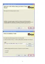
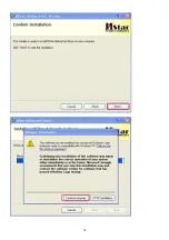
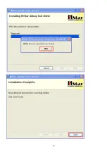
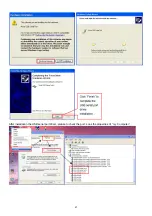
Страница 16: ...16 2 Connection 3 Install driver S1 If you use this ISP board first time First you need to install mstar driver...

Страница 17: ...17...

Страница 18: ...18...

Страница 19: ...19...

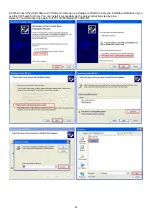
Страница 20: ...B port will pop up a Hardware Wizard to help you install the USB driver if you use this ISP board first time You can install it successfully as the below instruction step by step Remark The USB driver...

Страница 21: ...21 After installation the USB serial port driver please to check the port Look the properties of my Computer...

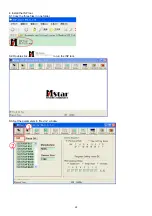
Страница 22: ...22 4 Install the ISP tool S1 Copy the three files in one folder S2 Double click to run the ISP tool S3 Set the parameters in Device window...

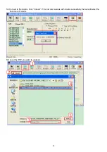
Страница 23: ...23 S4 Connect to the monitor Click Connect If the tool communicate with monitor successfully the tool will detect the flash type of monitor S5 Load the F W you want to upgrade...

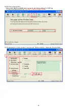
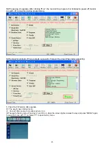
Страница 24: ...If the monitor has DVI or HDMI port you need to set restore address for HDCP key to avoid re program HDCP key 0x07D000 24KB for ACER T232HL S7 Set parameter in Auto window If you have set Restore add...

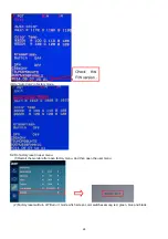
Страница 25: ...ssful upgrade When upgrade successful there will be green Pass letter appearing 5 Check the FW version after upgrade S1 The way to open factory menu 1 Connect VGA source to monitor and turn it on 2 Th...

Страница 26: ...factory mode S2 Do factory reset in user menu 1 Restart the monitor after open factory menu And then open the user menu 2 Factory reset will turn off Burn in mode which screen color switches among red...

Страница 27: ...ntry ISP Mode 1 Check the cables and ISP JIG are connected fluently 2 Click the Dis Con and click Connect again 3 AC off the monitor for a while and retry it 4 Change other vervion ISP program 4 Chang...

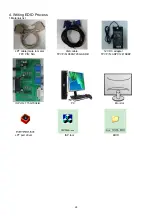
Страница 28: ...4 Writing EDID Process 1 Materials list LPT cable male to male VGA cable 12V DC adapter TPV P N N A TPV P N 089G728 GAA DB TPV P N ADPC12416BEP ISP JIG 715GT034 B PC Monitor LPT port driver ISP tool E...

Страница 29: ...ion 4 Prepare the EDID written S1 Change the EDID files name as below rule VGA EDID WA dat HDMI1 EDID WH dat HDMI2 EDID WH2 dat MHL1 EDID WHM dat MHL2 EDID WHM2 dat S2 Copy these six files to one fold...

Страница 30: ...30 5 Run the ISP tool S1 Double click the icon to open the tool S2 Select the EDID folder...

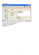
Страница 31: ...31 S3 Load EDID successful S4 Tick the Only connect VGA and write SN then click Debug Imformayion...

Страница 32: ...32 S5 type in the 22 digit S N S6 Start to writing Click write EDID to start writing When The green PASS appear the process is finished...

Страница 33: ...ion SN you can check the SN 6 Troubleshooting S1 Can t write 1 AC on the monitor and turn on it Restart the monitor 2 Take apart the monitor and connect the 7pin of EEPROM to GND to diable write prote...

Страница 34: ...AUTHORIZED SERVICE PROVIDERS your ACER office may have a DIFFERENT part number code from those given in the FRU list of this printed Service Guide You MUST use the local FRU list provided by your regi...

Страница 35: ...6YAA 23 T2DM2 001 LCD LM230WF3 SLP1 FQ TVEFQ 750GDB230F3P13N0AC 6M T27M2 002 HARNESS 6P 2008 6P SHJP 360mm PB TO PANEL 395G801406DK04 50 T27M2 007 LVDS CABLE 30P 30P A2004 260 MB TO PANEL 395G801830DL...

Страница 36: ...280MM PB TO USB 395G801405XH58 50 T27M2 004 BEZEL_BTM A34G370700201C0100 60 T27M2 001 REAR COVER A34G3706AEMA1L0130 60 T27M2 002 STAND BASE ASSY Q37G043100200000FH 60 T27M2 006 COVER HINGE A34G3701AEM...

Страница 37: ...37 MAIN FRAME Q15G204420101A00FJ 60 T27M2 005...

Страница 38: ...38 6 Trouble shooting instructions...

Страница 39: ...39...

Отзывы: