


Chapter 2
27
Setting a Password
Follow these steps as you set the user or the supervisor password:
1.
Use the
↑
and
↓
keys to highlight the Set Supervisor Password parameter and press the
Enter
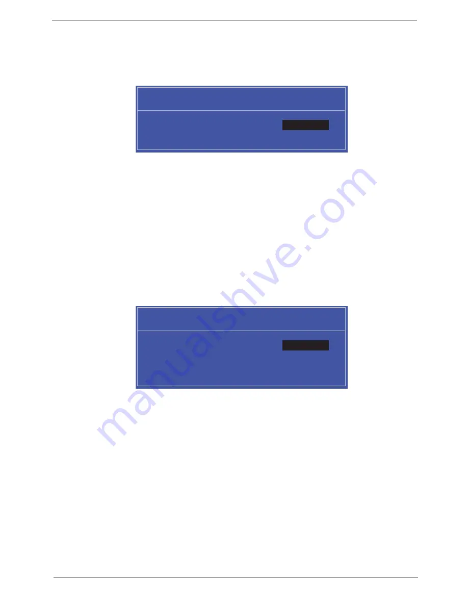
key. The
Set Supervisor Password box appears:
2.
Type a password in the “Enter New Password” field. The password length can not exceeds 8
alphanumeric characters (A-Z, a-z, 0-9, not case sensitive). Retype the password in the “Confirm New
Password” field.
IMPORTANT:
Be very careful when typing your password because the characters do not appear on the screen.
3.
Press
Enter
.
After setting the password, the computer sets the User Password parameter to “Set”.
4.
If desired, you can opt to enable the Password on boot parameter.
5.
When you are done, press F10 to save the changes and exit the BIOS Setup Utility.
Removing a Password
Follow these steps:
1.
Use the
↑
and
↓
keys to highlight the Set Supervisor Password parameter and press the
Enter
key. The
Set Password box appears:
2.
Type the current password in the Enter Current Password field and press
Enter
.
3.
Press
Enter
twice
without
typing anything in the Enter New Password and Confirm New Password fields.
The computer then sets the Supervisor Password parameter to “Clear”.
4.
When you have changed the settings, press
u
to save the changes and exit the BIOS Setup Utility.
S e t S u p e r v i s o r P a s s w o r d
E n t e r N e w P a s s w o r d [ ]
[ ]
C o n f i r m N e w P a s s w o r d [ ]
S e t S u p e r v i s o r P a s s w o r d
E n t e r C u r r e n t P a s s w o r d [ ]
[ ]
E n t e r N e w P a s s w o r d [ ]
C o n f i r m N e w P a s s w o r d [ ]
[ ]
Содержание Ferrari One 200
Страница 2: ...ii PRINTED IN TAIWAN ...
Страница 10: ...x Table of Contents ...
Страница 13: ...Chapter 1 3 System Block Diagram ...
Страница 48: ...38 Chapter 2 ...
Страница 60: ...50 Chapter 3 5 Lift the memory card out 6 Repeat steps 4 and 5 for the second memory card ...
Страница 63: ...Chapter 3 53 8 Remove the WLAN module ...
Страница 67: ...Chapter 3 57 4 Flip the keyboard over 5 Unlock the keyboard cable 6 Remove the keyboard cable and keyboard ...
Страница 74: ...64 Chapter 3 8 Lift the button board away ...
Страница 78: ...68 Chapter 3 8 Lift the I O board up by the inner edge and pull away on the angle ...
Страница 82: ...72 Chapter 3 7 Lift out the main board from the inside edge ...
Страница 84: ...74 Chapter 3 4 Lift the fan away from the main board ...
Страница 86: ...76 Chapter 3 2 Lift the RTC battery out of its holder ...
Страница 88: ...78 Chapter 3 4 Lift the speaker module out of the lower cover ...
Страница 90: ...80 Chapter 3 LCD Bracket Disassembly 2 2 5 4 86 TPK07 001 Step Screw Quantity Part No ...
Страница 95: ...Chapter 3 85 4 Lift the LCD panel out of the LCD module ...
Страница 100: ...90 Chapter 3 4 Remove the magnet 5 Pull the foil and antennas off the adhesive ...
Страница 108: ...98 Chapter 3 2 Press the bezel down around the edges ...
Страница 120: ...110 Chapter 3 2 Reconnect the Bluetooth cable Replacing the Button Board 1 Place the button board on the upper cover ...
Страница 124: ...114 Chapter 3 3 Press around the edges of the upper cover 4 Connect the button board cable to the main board ...
Страница 125: ...Chapter 3 115 5 Connect the IO cable to the IO card and main board ...
Страница 129: ...Chapter 3 119 2 Press the DIMM module down Replacing the 3G Module 1 Insert the 3G module ...
Страница 135: ...Chapter 3 125 Replacing the Dummy Card 1 Insert the dummy card until it clicks into place ...
Страница 136: ...126 Chapter 3 ...
Страница 156: ...146 Chapter 5 ...
Страница 168: ...158 Chapter 6 ...
Страница 180: ...170 ...
Страница 183: ...173 ...
Страница 184: ...174 ...


