


12
Chapter 1
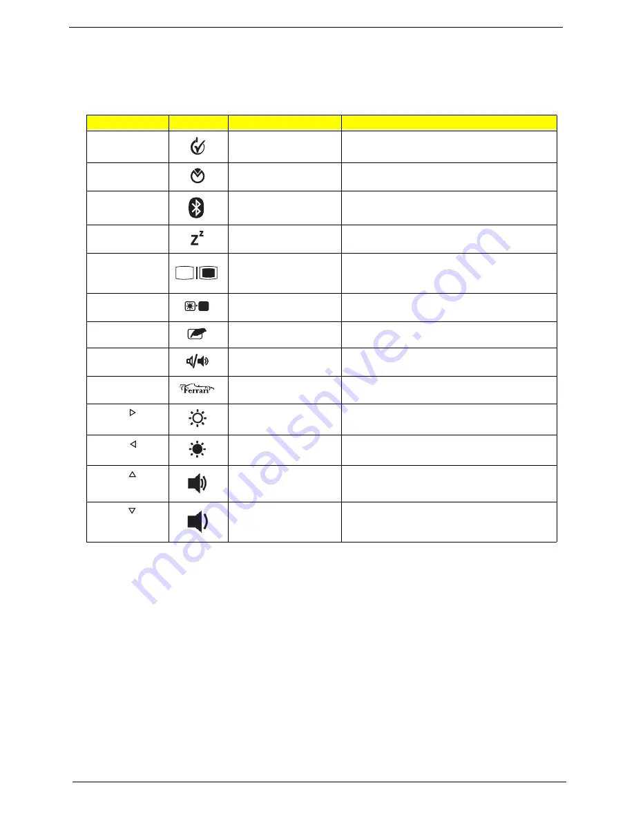
Hot Keys
The computer employs hotkeys or key combinations to access most of the computer's controls like screen
brightness and volume output.
To activate hotkeys, press and hold the
<Fn>
key before pressing the other key in the hotkey combination.
Hotkey
Icon
Function
Description
<Fn> + <F1>
Power management
Launch Windows power management.
<Fn> + <F2>
System Properties
Display the System Properties dialog box.
<Fn> + <F3>
Bluetooth
communication switch
Enables/disables the Bluetooth function.
<Fn> + <F4>
Sleep
Puts the computer in Sleep mode.
<Fn> + <F5>
Display toggle
Switches display output between the display
screen, external monitor (if connected) and
both.
<Fn> + <F6>
Screen blank
Turns the display screen backlight off to save
power. Press any key to return.
<Fn> + <F7>
Touchpad toggle
Turns the internal touchpad on and off.
<Fn> + <F8>
Speaker toggle
Turns the speakers on and off.
<Fn> + <F10>
Ferrari
Opens the Ferrari website.
<Fn> + < >
Brightness up
Increases the screen brightness.
<Fn> + < >
Brightness down
Decreases the screen brightness.
<Fn> + < >
Volume up
Increases the sound volume.
<Fn> + < >
Volume down
Decreases the sound volume.
<Fn> + <F
1
0>
Содержание Ferrari One 200
Страница 2: ...ii PRINTED IN TAIWAN ...
Страница 10: ...x Table of Contents ...
Страница 13: ...Chapter 1 3 System Block Diagram ...
Страница 48: ...38 Chapter 2 ...
Страница 60: ...50 Chapter 3 5 Lift the memory card out 6 Repeat steps 4 and 5 for the second memory card ...
Страница 63: ...Chapter 3 53 8 Remove the WLAN module ...
Страница 67: ...Chapter 3 57 4 Flip the keyboard over 5 Unlock the keyboard cable 6 Remove the keyboard cable and keyboard ...
Страница 74: ...64 Chapter 3 8 Lift the button board away ...
Страница 78: ...68 Chapter 3 8 Lift the I O board up by the inner edge and pull away on the angle ...
Страница 82: ...72 Chapter 3 7 Lift out the main board from the inside edge ...
Страница 84: ...74 Chapter 3 4 Lift the fan away from the main board ...
Страница 86: ...76 Chapter 3 2 Lift the RTC battery out of its holder ...
Страница 88: ...78 Chapter 3 4 Lift the speaker module out of the lower cover ...
Страница 90: ...80 Chapter 3 LCD Bracket Disassembly 2 2 5 4 86 TPK07 001 Step Screw Quantity Part No ...
Страница 95: ...Chapter 3 85 4 Lift the LCD panel out of the LCD module ...
Страница 100: ...90 Chapter 3 4 Remove the magnet 5 Pull the foil and antennas off the adhesive ...
Страница 108: ...98 Chapter 3 2 Press the bezel down around the edges ...
Страница 120: ...110 Chapter 3 2 Reconnect the Bluetooth cable Replacing the Button Board 1 Place the button board on the upper cover ...
Страница 124: ...114 Chapter 3 3 Press around the edges of the upper cover 4 Connect the button board cable to the main board ...
Страница 125: ...Chapter 3 115 5 Connect the IO cable to the IO card and main board ...
Страница 129: ...Chapter 3 119 2 Press the DIMM module down Replacing the 3G Module 1 Insert the 3G module ...
Страница 135: ...Chapter 3 125 Replacing the Dummy Card 1 Insert the dummy card until it clicks into place ...
Страница 136: ...126 Chapter 3 ...
Страница 156: ...146 Chapter 5 ...
Страница 168: ...158 Chapter 6 ...
Страница 180: ...170 ...
Страница 183: ...173 ...
Страница 184: ...174 ...


