


38
7-2
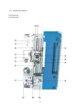
Apron & Saddle
1.
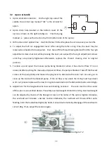
Apron lubrication location: On the right top side of the
saddle, the oil inlet cap marked “OIL” is the oil inlet for
apron.
○
A
2.
Apron drain hole located on the bottom cover of the
apron as shown on the right side figure. The drain plug
marked
○
A
(also see the chart on the front bottom side of the apron).
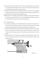
3.
Oil brand and oil replace time: Use Shell Tellus T-68 and replace the oil once every six months.
4.
To adjust the half nut engagement lever: After using the lathe a long time, the lever may be
loosened and needed to be adjusted. First, take off the thread chasing dial and find the four gib
adjustment screws. Second, while pressing the lever, also adjust the four gib adjustment screws
until they are properly tightened. Afterwards, replace the thread chasing dial to original
position.
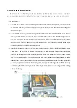
5.
To clean up and repair the manual pump being blocked or when it has small oil flow: If no oil
oozes out after pushing the manual pump several times, the pump is blocked. Take off the four set
screws of the pump body and loosen the plug lever to dismantle the cover nut. Use air gun to
clean up the inside of the blocked pump. If the oil flow is too small, the O-ring must have been
worn out, please replace with a new O-ring and assemble back the dismantled parts accordingly.
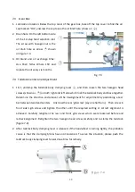
6.
Adjustment for the longitudinal & cross auto feeding overload: The cone clutch on the center
of the apron is an overload device. The safety overload weight limitation is 12 Kg. Overload weight
can be adjusted by means of the Hexagon screw on the center of the apron; tighten clockwise,
the overload will increase; unscrew counter-clockwise, the overload will loosen. When auto-
feeding, hold the handwheel tightly by hand, it should automatically disengage if the overload is
set at 12Kg. If not, adjust the tension again.
○
D
Figure 7-2
Содержание Dynamic 1722S
Страница 6: ...6 ...
Страница 7: ...7 ...
Страница 15: ...15 ...
Страница 16: ...16 ...
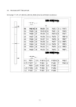
Страница 30: ...30 0 27 MD2 0 82 PD10 0 12 MD2 ...
Страница 36: ...36 6 4 Lubrication Location A Oil input cap B Oil drain hole ...
Страница 43: ...43 ...
Страница 44: ...44 8 1 Headstock ...
Страница 50: ...50 8 2 Gearbox ...
Страница 56: ...56 3 Apron ...
Страница 62: ...62 8 4 Bed and Base ...
Страница 65: ...65 8 5 Break System ...
Страница 68: ...68 8 6 Carriage and Crossfeed ...
Страница 70: ...70 35 Washer wave type 6210 2 36 Set screw M6xP1 0x10L 1 ...
Страница 72: ...72 70 Tool post square export 1 1003512802 1003512606 local 1 1003512704 1003512508 ...
Страница 73: ...73 8 7 Tailstock ...
Страница 75: ...75 38 Case 1 1122100502 1122100502 1122100502 39 Wiper 1 1122100100 1122100100 1122100100 ...
Страница 77: ...77 8 8 Steady Rest ...
Страница 79: ...79 8 9 Follow Rest ...
Страница 81: ...81 8 10 Coolant System ...


