


23
4-6
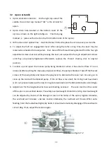
Transmission & Stop of Gear Box
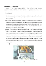
Open the end cover to find the gear train transmitting from headstock to gear box, position the
forward/reverse shifting lever (#4 of item 1-1) to the right side, the spindle will rotate forward; to the
left side it will reverse; to the Neutral position it will stop. Do not change the gears while spindle is
turning.
4-7
Gear Box Operation
1.
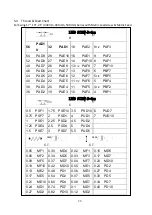
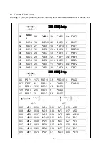
Threading:
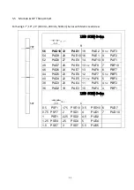
With the special design, there is no need to re-arrange the back gears for threading. Please refer
to the ‘threading & feeding table’ and the thread/feed selection lever (#5 of item 1-1),
thread/feed shifting lever (#6 of item 1-1) and 10-step feed selection dial (#7 of item 1-1)
accordingly.
2.
Auto feeding
Also select the appropriate auto feeding rate by positioning the thread/feed selection lever ((#5
of item 1-1), thread/feed shifting lever (#6 of item 1-1) and 10-step feed selection dial (#7 of item
1-1) as indicated on the “threading and feeding table”.
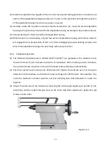
4-8
Manual Operation
First, position both the halt nut engage lever #18, and forward/reverse shifting lever (#4 of item
1-1) to ‘N’ position to operate the apron handwheel #13 cross slide handle #14, and compound
rest handle #32 easily.
It feeds 20mm (0.8”) per revolution of apron handwheel. The dial on cross slide is graduated
0.02mm (0.001”) and revolute 6.36mm (0.25”) per turn. For compound rest, it is graduated
0.04mm (0.001”) per calibration, and feeds 2.08mm (0.2”) per revolution.
The tool post can be rotated clockwise after loosen the tool post clamping lever (#36 of item 1-1).
Then position the turret and tighten the clamping lever again. For fixing the apron at any position,
just tighten the saddle clamping lever #20. For cross slide and compound rest, please screw tightly
the set screws beside the taper pin.
Содержание Dynamic 1722S
Страница 6: ...6 ...
Страница 7: ...7 ...
Страница 15: ...15 ...
Страница 16: ...16 ...
Страница 30: ...30 0 27 MD2 0 82 PD10 0 12 MD2 ...
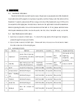
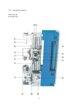
Страница 36: ...36 6 4 Lubrication Location A Oil input cap B Oil drain hole ...
Страница 43: ...43 ...
Страница 44: ...44 8 1 Headstock ...
Страница 50: ...50 8 2 Gearbox ...
Страница 56: ...56 3 Apron ...
Страница 62: ...62 8 4 Bed and Base ...
Страница 65: ...65 8 5 Break System ...
Страница 68: ...68 8 6 Carriage and Crossfeed ...
Страница 70: ...70 35 Washer wave type 6210 2 36 Set screw M6xP1 0x10L 1 ...
Страница 72: ...72 70 Tool post square export 1 1003512802 1003512606 local 1 1003512704 1003512508 ...
Страница 73: ...73 8 7 Tailstock ...
Страница 75: ...75 38 Case 1 1122100502 1122100502 1122100502 39 Wiper 1 1122100100 1122100100 1122100100 ...
Страница 77: ...77 8 8 Steady Rest ...
Страница 79: ...79 8 9 Follow Rest ...
Страница 81: ...81 8 10 Coolant System ...


