


4-8
Troubleshooting
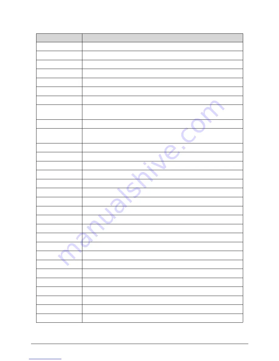
0x3A
Post-Memory North Bridge initialization (North Bridge module specific)
0x3B
Post-Memory South Bridge initialization is started
0x3C
Post-Memory South Bridge initialization (South Bridge module specific)
0x3D
Post-Memory South Bridge initialization (South Bridge module specific)
0x3E
Post-Memory South Bridge initialization (South Bridge module specific)
0x3F-0x4E
OEM post memory initialization codes
0x4F
DXE IPL is started
0x50
Memory initialization error. Invalid memory type or incompatible memory
speed
0x51
Memory initialization error. SPD reading has failed
0x52
Memory initialization error. Invalid memory size or memory modules do
not match.
0x53
Memory initialization error. No usable memory detected
0x54
Unspecified memory initialization error.
0x55
Memory not installed
0x56
Invalid CPU type or Speed
0x57
CPU mismatch
0x58
CPU self test failed or possible CPU cache error
0x59
CPU micro-code is not found or micro-code update is failed
0x5A
Internal CPU error
0x5B
reset PPI is not available
0x5C-0x5F
Reserved for future AMI error codes
0xE0
S3 Resume is stared (S3 Resume PPI is called by the DXE IPL)
0xE1
S3 Boot Script execution
0xE2 Video
repost
0xE3
OS S3 wake vector call
0xE4-0xE7
Reserved for future AMI progress codes
0xE8
S3 Resume Failed in PEI
0xE9
S3 Resume PPI not Found
0xEA
S3 Resume Boot Script Error
0xEB
S3 OS Wake Error
0xEC-0xEF
Reserved for future AMI error codes
Table 4-2.
Checkpoint
Description
Содержание Aspire Z3170
Страница 1: ...Acer AZ3170 AZ3171 SERVICEGUIDE ...
Страница 2: ...ii ...
Страница 6: ...1 iv ...
Страница 7: ...CHAPTER 1 Hardware Specifications ...
Страница 26: ...1 20 Hardware Specifications and Configurations M B Placement 0 ...
Страница 29: ...Hardware Specifications and Configurations 1 23 Block Diagram 0 ...
Страница 30: ...1 24 Hardware Specifications and Configurations ...
Страница 31: ...CHAPTER 2 System Utilities ...
Страница 36: ...2 6 System Utilities Advanced 0 Advanced Miscellaneous 0 ...
Страница 48: ...2 18 System Utilities 8 Flash BIOS is finished ...
Страница 51: ...System Utilities 2 21 8 Select Save Exit Setup and press Enter key 9 Select Yes and press Enter key ...
Страница 52: ...2 22 System Utilities 10 Flash BIOS is finished ...
Страница 54: ...2 24 System Utilities 9 Select Yes and press Enter key 10 Select Save Exit Setup and press Enter key ...
Страница 55: ...System Utilities 2 25 11 Select Yes and press Enter key 12 Flash BIOS is finished ...
Страница 58: ...2 28 System Utilities ...
Страница 62: ...2 32 System Utilities ...
Страница 63: ...CHAPTER 3 System Disassembly and Assembly ...
Страница 66: ...3 4 ...
Страница 74: ...3 12 System Disassembly and Assembly First open one top side then open the other top side ...
Страница 75: ...System Disassembly and Assembly 3 13 Open the low side ...
Страница 85: ...System Disassembly and Assembly 3 23 Removing the Display Card 0 Unplug the DVI cable ...
Страница 95: ...System Disassembly and Assembly 3 33 Remove the heatsink in the direction as indicated by the arrow ...
Страница 97: ...System Disassembly and Assembly 3 35 Remove the CPU ...
Страница 103: ...System Disassembly and Assembly 3 41 ...
Страница 108: ...3 46 System Disassembly and Assembly Remove the base pan in the direction as indicated by the arrow ...
Страница 111: ...System Disassembly and Assembly 3 49 Unplug the LCD power cable Take out the LCD with bracket ...
Страница 118: ...3 56 System Disassembly and Assembly 4 Plug the LCD power cable NOTE NOTE Be careful that do not plug it on backward ...
Страница 121: ...System Disassembly and Assembly 3 59 Lock all the latch Plug the LVDS cable ...
Страница 122: ...3 60 System Disassembly and Assembly Screw 8 screws to fix it Table 3 28 ID Size Quantity Screw Type M3X5L B 8 ...
Страница 131: ...System Disassembly and Assembly 3 69 Table 3 35 ID Size Quantity Screw Type M4 6L K 4 ...
Страница 133: ...System Disassembly and Assembly 3 71 Lock the latch in the direction as indicated by the arrow ...
Страница 134: ...3 72 System Disassembly and Assembly Replacing the Memory 0 1 Instal the lower memory 2 Instal the upper memory ...
Страница 138: ...3 76 System Disassembly and Assembly Plug the DVI cable and lock 2 VGA locks ...
Страница 145: ...System Disassembly and Assembly 3 83 Attach the mylar to cover the camera ...
Страница 152: ...3 90 System Disassembly and Assembly 4 Attach the mylar as the location shown in the picture ...
Страница 156: ...3 94 System Disassembly and Assembly N A 4 Table 3 45 ID Size Quantity Screw Type ...
Страница 158: ...3 96 System Disassembly and Assembly Screw 9 screws to fix it Table 3 46 ID Size Quantity Screw Type M3X5L B 9 ...
Страница 162: ...3 100 System Disassembly and Assembly Install the hinge cover ...
Страница 163: ...System Disassembly and Assembly 3 101 Thermal Pad location on base pan 0 ...
Страница 165: ...System Disassembly and Assembly 3 103 AMD 6570 0 Attach the thermal pad on VGA memories ...
Страница 166: ...3 104 System Disassembly and Assembly ...
Страница 167: ...CHAPTER 4 Troubleshooting ...
Страница 180: ...4 14 Troubleshooting Following program s prompt in order as up right low left press the proper hole by using the stylus ...
Страница 183: ...Troubleshooting 4 17 Pressing the 25 calibration points in proper hole by using the stylus ...
Страница 187: ...CHAPTER 5 Jumper and Connector Locations ...
Страница 188: ...5 2 Jumper Setting 5 4 Setting Jumper 5 4 ...
Страница 189: ...Jumper and Connector Locations 5 3 Jumper and Connector Locations ...
Страница 191: ...Jumper and Connector Locations 5 5 This illustration shows a 3 pin jumper Pins 1 and 2 are SHORT ...
Страница 192: ...5 6 Jumper and Connector Locations ...
Страница 193: ...CHAPTER 6 FRU List ...
Страница 194: ...6 2 AZ3170 AZ3171 Exploded Diagrams 6 4 FRU List 6 6 ...