


System Disassembly and Assembly
3-65
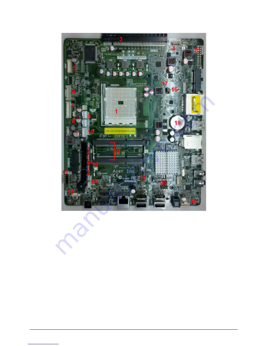
1. Unplug all the cable which connected to motherboard as below:
1. FM1 CPU socket
2. DDRIII DIMM slot
3. PCIE x16 slot
4. Camera module connector
5. LCD connector
6. Converter connector
7. 3D scalar connector
8. Key Pad connector
9. CPU fan connector
10. SATA Power connector
11. Front Panel connector
12. Bluetooth connector
13. Touch Panel connector
14. IR connector
Содержание Aspire Z3170
Страница 1: ...Acer AZ3170 AZ3171 SERVICEGUIDE ...
Страница 2: ...ii ...
Страница 6: ...1 iv ...
Страница 7: ...CHAPTER 1 Hardware Specifications ...
Страница 26: ...1 20 Hardware Specifications and Configurations M B Placement 0 ...
Страница 29: ...Hardware Specifications and Configurations 1 23 Block Diagram 0 ...
Страница 30: ...1 24 Hardware Specifications and Configurations ...
Страница 31: ...CHAPTER 2 System Utilities ...
Страница 36: ...2 6 System Utilities Advanced 0 Advanced Miscellaneous 0 ...
Страница 48: ...2 18 System Utilities 8 Flash BIOS is finished ...
Страница 51: ...System Utilities 2 21 8 Select Save Exit Setup and press Enter key 9 Select Yes and press Enter key ...
Страница 52: ...2 22 System Utilities 10 Flash BIOS is finished ...
Страница 54: ...2 24 System Utilities 9 Select Yes and press Enter key 10 Select Save Exit Setup and press Enter key ...
Страница 55: ...System Utilities 2 25 11 Select Yes and press Enter key 12 Flash BIOS is finished ...
Страница 58: ...2 28 System Utilities ...
Страница 62: ...2 32 System Utilities ...
Страница 63: ...CHAPTER 3 System Disassembly and Assembly ...
Страница 66: ...3 4 ...
Страница 74: ...3 12 System Disassembly and Assembly First open one top side then open the other top side ...
Страница 75: ...System Disassembly and Assembly 3 13 Open the low side ...
Страница 85: ...System Disassembly and Assembly 3 23 Removing the Display Card 0 Unplug the DVI cable ...
Страница 95: ...System Disassembly and Assembly 3 33 Remove the heatsink in the direction as indicated by the arrow ...
Страница 97: ...System Disassembly and Assembly 3 35 Remove the CPU ...
Страница 103: ...System Disassembly and Assembly 3 41 ...
Страница 108: ...3 46 System Disassembly and Assembly Remove the base pan in the direction as indicated by the arrow ...
Страница 111: ...System Disassembly and Assembly 3 49 Unplug the LCD power cable Take out the LCD with bracket ...
Страница 118: ...3 56 System Disassembly and Assembly 4 Plug the LCD power cable NOTE NOTE Be careful that do not plug it on backward ...
Страница 121: ...System Disassembly and Assembly 3 59 Lock all the latch Plug the LVDS cable ...
Страница 122: ...3 60 System Disassembly and Assembly Screw 8 screws to fix it Table 3 28 ID Size Quantity Screw Type M3X5L B 8 ...
Страница 131: ...System Disassembly and Assembly 3 69 Table 3 35 ID Size Quantity Screw Type M4 6L K 4 ...
Страница 133: ...System Disassembly and Assembly 3 71 Lock the latch in the direction as indicated by the arrow ...
Страница 134: ...3 72 System Disassembly and Assembly Replacing the Memory 0 1 Instal the lower memory 2 Instal the upper memory ...
Страница 138: ...3 76 System Disassembly and Assembly Plug the DVI cable and lock 2 VGA locks ...
Страница 145: ...System Disassembly and Assembly 3 83 Attach the mylar to cover the camera ...
Страница 152: ...3 90 System Disassembly and Assembly 4 Attach the mylar as the location shown in the picture ...
Страница 156: ...3 94 System Disassembly and Assembly N A 4 Table 3 45 ID Size Quantity Screw Type ...
Страница 158: ...3 96 System Disassembly and Assembly Screw 9 screws to fix it Table 3 46 ID Size Quantity Screw Type M3X5L B 9 ...
Страница 162: ...3 100 System Disassembly and Assembly Install the hinge cover ...
Страница 163: ...System Disassembly and Assembly 3 101 Thermal Pad location on base pan 0 ...
Страница 165: ...System Disassembly and Assembly 3 103 AMD 6570 0 Attach the thermal pad on VGA memories ...
Страница 166: ...3 104 System Disassembly and Assembly ...
Страница 167: ...CHAPTER 4 Troubleshooting ...
Страница 180: ...4 14 Troubleshooting Following program s prompt in order as up right low left press the proper hole by using the stylus ...
Страница 183: ...Troubleshooting 4 17 Pressing the 25 calibration points in proper hole by using the stylus ...
Страница 187: ...CHAPTER 5 Jumper and Connector Locations ...
Страница 188: ...5 2 Jumper Setting 5 4 Setting Jumper 5 4 ...
Страница 189: ...Jumper and Connector Locations 5 3 Jumper and Connector Locations ...
Страница 191: ...Jumper and Connector Locations 5 5 This illustration shows a 3 pin jumper Pins 1 and 2 are SHORT ...
Страница 192: ...5 6 Jumper and Connector Locations ...
Страница 193: ...CHAPTER 6 FRU List ...
Страница 194: ...6 2 AZ3170 AZ3171 Exploded Diagrams 6 4 FRU List 6 6 ...