


Chapter 1
25
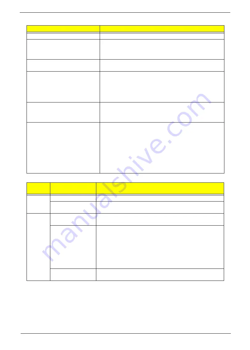
System LED Indicator
Power Specification
Item
Specification
Lock
N/A
System state
•
Blue color solid on: System on
•
Blue color off: System off
•
Orange color blinking: Sleep state
HDD access state
Blue color: Fast blinking when HDD/SSD/Card reader is running
or accessing to data
Wireless state
Dual color (Blue/Orange)
3G only: Blue
3G+WiFi: Blue
WiFi only: Orange
Both off: N/A
Power button backlight
•
Blue color solid on: System on
•
Blue color off: System off, sleep and hibernation state
•
Blue color solid on: System on
Blue color off: System off, sleep and
hibernation state
Charging
•
Orange solid on - Battery charging with AC
•
Blue color solid on - Battery full
•
Orange blinking - Battery abnormal stop charge or battery in
low power state
Discharging
•
Orange and blinking - Battery in critical low state
•
Orange and blue color off - Discharging state
Legacy
Mode
ACPI Mode
Power Management
Off
Mech. Off (G3)
All devices in the system are turned off completely.
Soft Off (G2/S5)
OS initiated shutdown. All devices in the system are turned off
completely.
On
Working (G0/S0)
Individual devices such as the CPU and hard disk may be power
managed in this state.
S3 Sleeping State
CPU set power down
VGA suspend
PCMCIA suspend
Audio power down
Hard Disk power down
CD-ROM power down
Super I/O low power mode
S4 Sleeping State
Also called Hibernate state. The system saves all system states
and data onto disk prior to powering off the whole system.
Содержание Aspire One D255 Series
Страница 6: ...VI ...
Страница 10: ...X Table of Contents ...
Страница 36: ...26 Chapter 1 ...
Страница 53: ...Chapter 2 43 3 Execute MAC BAT to write MAC information to eeprom ...
Страница 62: ...52 Chapter 3 5 Unlock the FPC 6 Remove the FPC and the keyboard ...
Страница 90: ...80 Chapter 3 8 Remove the LCD module from the chassis ...
Страница 111: ...Chapter 3 101 6 Place the left antenna cables into the cable guides on the bottom cover 7 Replace the DC In power jack ...
Страница 121: ...Chapter 3 111 3 Adhere the button board FFC to the upper cover 4 Connect and lock the touchpad FFC to the connector ...
Страница 124: ...114 Chapter 3 5 Connect and lock the LED FFC to the connector 6 Connect and lock the touchpad FFC to the connector ...
Страница 133: ...Chapter 3 123 2 Push the battery lock latch in the direction shown to secure the battery ...
Страница 134: ...124 Chapter 3 ...
Страница 156: ...146 Chapter 4 ...
Страница 168: ...158 Chapter 6 LOWER CASE 60 SDE02 002 LOGIC DOOR 60 SDE02 003 HDD HOUSING 33 SDE02 001 Category Description P N ...
Страница 264: ...254 Chapter 3 ...
Страница 270: ...260 Appendix C ...


