


132
Chapter 4
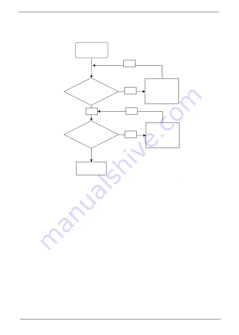
Internal Microphone Failure
If the internal
Microphone
fails, perform the following actions one at a time to correct the problem. Do not
replace a non-defective FRUs:
Microphone Problems
If internal or external
Microphones
do no operate correctly, perform the following actions one at a time to
correct the problem.
1.
Check that the microphone is enabled. Navigate to
Start
´
Control
Panel
´
Hardware
and
Sound
´
Sound
and select the
Recording
tab.
2.
Right-click on the
Recording
tab and select
Show
Disabled
Devices
(clear by default).
3.
The microphone appears on the
Recording
tab.
4.
Right-click on the microphone and select
Enable
.
5.
Select the microphone then click
Properties
. Select the
Levels
tab.
6.
Increase the volume to the maximum setting and click
OK
.
7.
Test the microphone hardware:
a.
Select the microphone and click
Configure
.
b.
Select
Set up microphone
.
c.
Select the microphone type from the list and click
Next
.
d.
Follow the onscreen prompts to complete the test.
8.
If the Issue is still not resolved, see “Online Support Information” on page 259.
Start
Check M/B
Mic cable
Re-assemble
the MIC cable
to M/B
OK
NG
Check MIC
wire of LCD
module
OK
Swap MIC wire
of LCD module
OK
NG
Swap M/B
Содержание Aspire One D255 Series
Страница 6: ...VI ...
Страница 10: ...X Table of Contents ...
Страница 36: ...26 Chapter 1 ...
Страница 53: ...Chapter 2 43 3 Execute MAC BAT to write MAC information to eeprom ...
Страница 62: ...52 Chapter 3 5 Unlock the FPC 6 Remove the FPC and the keyboard ...
Страница 90: ...80 Chapter 3 8 Remove the LCD module from the chassis ...
Страница 111: ...Chapter 3 101 6 Place the left antenna cables into the cable guides on the bottom cover 7 Replace the DC In power jack ...
Страница 121: ...Chapter 3 111 3 Adhere the button board FFC to the upper cover 4 Connect and lock the touchpad FFC to the connector ...
Страница 124: ...114 Chapter 3 5 Connect and lock the LED FFC to the connector 6 Connect and lock the touchpad FFC to the connector ...
Страница 133: ...Chapter 3 123 2 Push the battery lock latch in the direction shown to secure the battery ...
Страница 134: ...124 Chapter 3 ...
Страница 156: ...146 Chapter 4 ...
Страница 168: ...158 Chapter 6 LOWER CASE 60 SDE02 002 LOGIC DOOR 60 SDE02 003 HDD HOUSING 33 SDE02 001 Category Description P N ...
Страница 264: ...254 Chapter 3 ...
Страница 270: ...260 Appendix C ...


