


Chapter 5
149
Clearing Password Check and BIOS Recovery
This section provide you the standard operating procedures of clearing password and BIOS recovery for the
computer. There is one Hardware Open Gap on the mainboard for clearing password check, and one Hotkey
for enabling BIOS Recovery.
Clearing Password Check
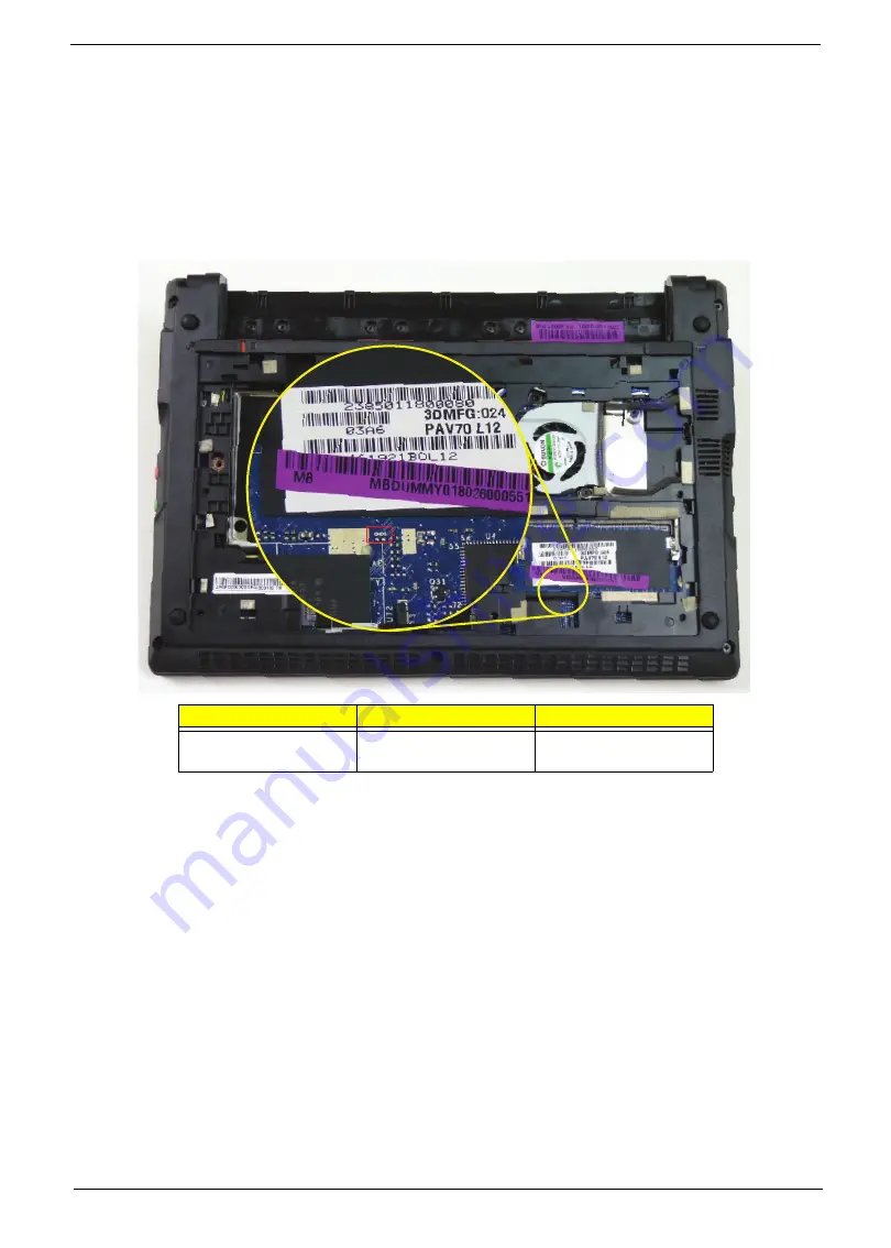
Hardware Open Gap Description is as follows:
Steps for Clearing BIOS Password Check
If users set BIOS Password (Supervisor Password and/or User Password) for a security reason, BIOS will ask
the password during systems POST or when systems enter to BIOS Setup menu. However, once it is
necessary to bypass the password check, users need to short the HW Gap to clear the password by the
following steps:
1.
Power Off the system, and remove HDD, AC and Battery from the machine.
2.
Disconnect the RTC Battery cable and locate the CMOS jumper in the DIMM bay.
3.
Use an electric conductivity tool to short the two points of the HW Gap.
4.
Plug in AC, keep the short condition on the HW Gap, and press Power Button to power on the system till BIOS
POST finish. Then remove the tool from the HW Gap.
5.
Restart system. Press
F2
key to enter BIOS Setup menu.
6.
If there is no Password request, BIOS Password is cleared. Otherwise, please follow the steps and try again.
NOTE:
These steps are only for clearing BIOS Password (Supervisor Password and User Password).
Item
Description
Location
CMOS
Clear CMOS Jumper
Located near DIMM
Module
Содержание Aspire One D255 Series
Страница 6: ...VI ...
Страница 10: ...X Table of Contents ...
Страница 36: ...26 Chapter 1 ...
Страница 53: ...Chapter 2 43 3 Execute MAC BAT to write MAC information to eeprom ...
Страница 62: ...52 Chapter 3 5 Unlock the FPC 6 Remove the FPC and the keyboard ...
Страница 90: ...80 Chapter 3 8 Remove the LCD module from the chassis ...
Страница 111: ...Chapter 3 101 6 Place the left antenna cables into the cable guides on the bottom cover 7 Replace the DC In power jack ...
Страница 121: ...Chapter 3 111 3 Adhere the button board FFC to the upper cover 4 Connect and lock the touchpad FFC to the connector ...
Страница 124: ...114 Chapter 3 5 Connect and lock the LED FFC to the connector 6 Connect and lock the touchpad FFC to the connector ...
Страница 133: ...Chapter 3 123 2 Push the battery lock latch in the direction shown to secure the battery ...
Страница 134: ...124 Chapter 3 ...
Страница 156: ...146 Chapter 4 ...
Страница 168: ...158 Chapter 6 LOWER CASE 60 SDE02 002 LOGIC DOOR 60 SDE02 003 HDD HOUSING 33 SDE02 001 Category Description P N ...
Страница 264: ...254 Chapter 3 ...
Страница 270: ...260 Appendix C ...


