Chapter 2
27
Main
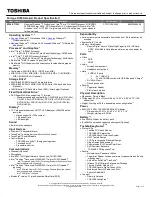
The Main screen allows the user to set the system time and date as well as enable and disable boot option
and recovery.
NOTE: The screen above is for your reference only. Actual values may differ.
The table below describes the parameters in this screen. Settings in boldface are the default and suggested
parameter settings.
Parameter
Description
Format/Option
System Time
Sets the system time. The hours are displayed with 24-
hour format.
Format: HH:MM:SS
(hour:minute:second)
System Date
Sets the system date.
Format MM/DD/YYYY
(month/day/year)
System Memory
This field reports system memory size.
N/A
Total Memory
This field reports the memory size of the system.
Memory size is fixed to 4096MB.
N/A
Video Memory
Shows the video memory size. VGA Memory size=32 MB
N/A
Quiet Boot
This will hide POST messages while booting.
Option: Enabled or Disabled
Network Boot
Enables, disables the system boot from LAN (remote
server).
Option: Enabled or Disabled
F12 Boot Menu
Enables, disables Boot Menu during POST.
Option: Enabled or Enabled
D2D Recovery
Enables, disables D2D Recovery function. The function
allows the user to create a hidden partition on hard disc
drive to store operation system and restore the system
to factory defaults.
Option: Enabled or Disabled
SATA Mode
Control the mode in which the SATA controller should
operate.
Option: AHCI or IDE
Item S pecificHelp
This is th
e help for
the
hour field. Valid range
is from 0
to 23.
INCREASE/R
EDUCE: F5/
F 1
E S C
Help
Exit
Select Item
Select Menu
Change V alues
Select
SubMenu
E n t e r
F 9
F 10
Setup Default
Save and Exit
v19:
10:59v
v06/09/20
09v
640 K
4096 MB
v64MBv
vEnabledv
vEnabledv
vDisabledv
vEnabledv
vAHCI Modev
v19:
10:59v
v06/09/20
09v
640 K
4096 MB
v64MBv
vEnabledv
vEnabledv
vDisabledv
vEnabledv
vAHCI Modev
System Time:
System Date:
System Memory:
Total Memory:
Video Memory:
Quiet Boot
Network Boot
F12 Boot Menu
D2D Recovery
SATA Mode
System Time:
System Date:
System Memory:
Total Memory:
Video Memory:
Quiet Boot
Network Boot
F12 Boot Menu
D2D Recovery
SATA Mode
F 5 / F 6
InsydeH20 Setup Utility
Boot
Exit
Security
Information Main
Содержание ASPIRE ONE 1410
Страница 6: ...VI...
Страница 10: ...X Table of Contents...
Страница 34: ...24 Chapter 1...
Страница 50: ...40 Chapter 2...
Страница 59: ...Chapter 3 49 9 Detach the HDD board...
Страница 61: ...Chapter 3 51 5 Pull the memory module out 6 Repeat steps 4 and 5 for the second memory module...
Страница 73: ...Chapter 3 63 7 Unlock the touch pad FCC and pull the cable away...
Страница 77: ...Chapter 3 67 4 Lift off the LCD Board 5 Unlock and remove the LED board FCC from the mainboard...
Страница 87: ...Chapter 3 77 4 Pull the cables away from the two adhesive locations 5 Lift the modules away...
Страница 91: ...Chapter 3 81 5 Roll the bezel up and away from the hinges...
Страница 94: ...84 Chapter 3 4 Lift the LCD panel out lifting the bottom of the panel first...
Страница 99: ...Chapter 3 89 7 Lift up the right antenna 8 Pull the right antenna cable away from the LCD module...
Страница 106: ...96 Chapter 3 3 Apply adhesive and stick the microphone down...
Страница 113: ...Chapter 3 103 Replacing the RTC Battery 1 Place the RTC battery into the holding clips on the main board...
Страница 117: ...Chapter 3 107 3 Connect the speaker connector...
Страница 135: ...Chapter 3 125 4 Tighten the four captive screws...
Страница 137: ...Chapter 3 127 4 Place the HDD cover in from one corner 5 Tighten the two captive screws...
Страница 138: ...128 Chapter 3 Replacing the Battery 1 Slide the battery into position 2 Close the locking latch...
Страница 139: ...Chapter 3 129 Replace the Dummy Card Push the dummy card into the slot until it clicks into place...
Страница 140: ...130 Chapter 3...
Страница 240: ...230 Appendix A...
Страница 250: ...240 Appendix B...
Страница 252: ...242...
Страница 255: ...245...
Страница 256: ...246...