


Chapter 1
7
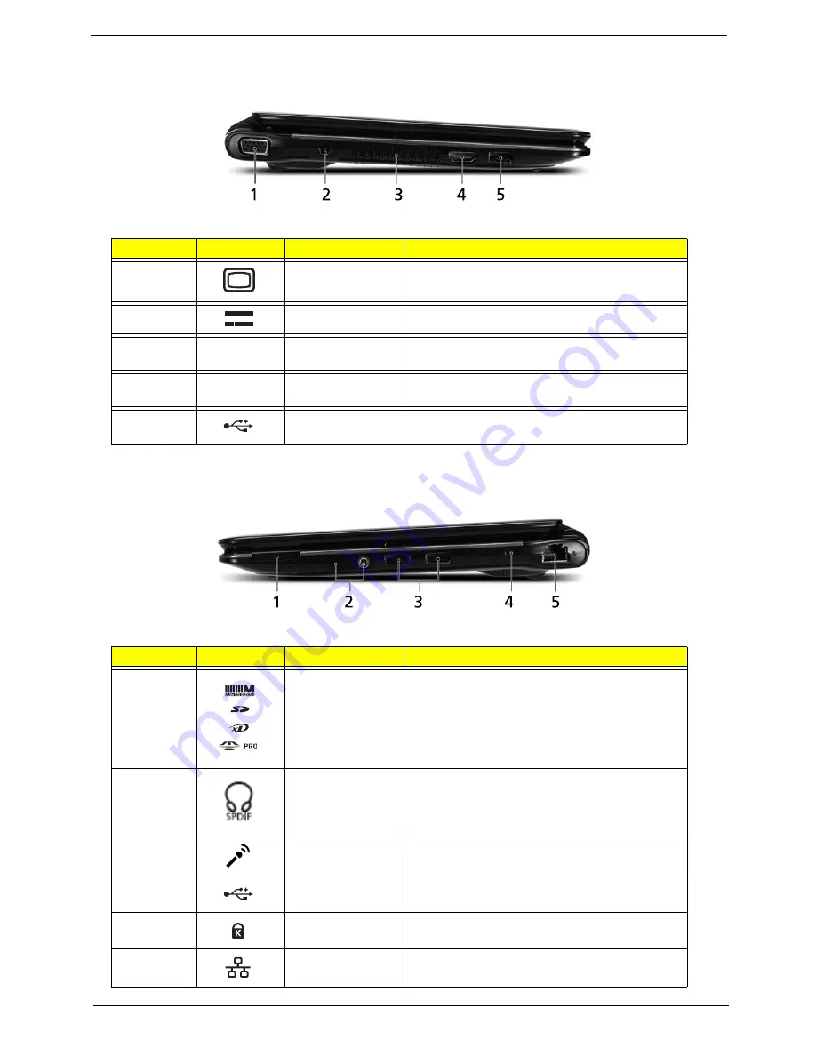
Left View
Right View
No.
Icon
Item
Description
1
External display
(VGA) port
Connects to a display device (e.g. external,
LCD monitor, LCD projector).
2
DC-in jack
Connects to an AC adapter.
3
Ventilation slots
Enable the computer to stay cool, even after
prolonged use.
4
HDMI
HDMI port
Supports high definition digital video
connections.
5
USB 2.0 port
Connects to USB 2.0 devices (e.g., USB
mouse, USB camera).
No.
Icon
Item
Description
1
Multi-in-one card
reader
Accepts Secure Digital (SD),
MultiMediaCard(MMC), Memory Stick(MS),
Memory Stick PRO (MS PRO), xD-Picture
Card (xD).
Note: Push to remove/install the card. ONly
one card can operate at any given time.
2
Headphones/
speaker/line-out
jack with S/PDIF
support.
Connects to audio line-out devices (e.g.,
speakers, headphones).
Microphone-in
jack
Accepts inputs from external microphones.
3
USB 2.0 port
Connects to USB 2.0 devices (e.g. USB
mouse).
4
Kensington lock
slot
Connects to a Kensington-compatible
computer security lock.
5
Ethernet RJ-45)
port
Connects to an Ethernet 10/100/1000-based
network.
g
Содержание ASPIRE ONE 1410
Страница 6: ...VI...
Страница 10: ...X Table of Contents...
Страница 34: ...24 Chapter 1...
Страница 50: ...40 Chapter 2...
Страница 59: ...Chapter 3 49 9 Detach the HDD board...
Страница 61: ...Chapter 3 51 5 Pull the memory module out 6 Repeat steps 4 and 5 for the second memory module...
Страница 73: ...Chapter 3 63 7 Unlock the touch pad FCC and pull the cable away...
Страница 77: ...Chapter 3 67 4 Lift off the LCD Board 5 Unlock and remove the LED board FCC from the mainboard...
Страница 87: ...Chapter 3 77 4 Pull the cables away from the two adhesive locations 5 Lift the modules away...
Страница 91: ...Chapter 3 81 5 Roll the bezel up and away from the hinges...
Страница 94: ...84 Chapter 3 4 Lift the LCD panel out lifting the bottom of the panel first...
Страница 99: ...Chapter 3 89 7 Lift up the right antenna 8 Pull the right antenna cable away from the LCD module...
Страница 106: ...96 Chapter 3 3 Apply adhesive and stick the microphone down...
Страница 113: ...Chapter 3 103 Replacing the RTC Battery 1 Place the RTC battery into the holding clips on the main board...
Страница 117: ...Chapter 3 107 3 Connect the speaker connector...
Страница 135: ...Chapter 3 125 4 Tighten the four captive screws...
Страница 137: ...Chapter 3 127 4 Place the HDD cover in from one corner 5 Tighten the two captive screws...
Страница 138: ...128 Chapter 3 Replacing the Battery 1 Slide the battery into position 2 Close the locking latch...
Страница 139: ...Chapter 3 129 Replace the Dummy Card Push the dummy card into the slot until it clicks into place...
Страница 140: ...130 Chapter 3...
Страница 240: ...230 Appendix A...
Страница 250: ...240 Appendix B...
Страница 252: ...242...
Страница 255: ...245...
Страница 256: ...246...


