84
Chapter 3
Removing the LCD Module
1.
See “Removing the Battery Pack” on page 54.
2.
See “Removing the SD dummy card” on page 55.
3.
See “Removing the ExpressCard dummy card” on page 56.
4.
See “Removing the Lower Cover” on page 56.
5.
See “Removing the TV Tuner Board Modules” on page 58.
6.
See “Removing the TV Tuner Board Modules” on page 58.
7.
See “Removing the Middle Cover” on page 73.
8.
See “Removing the Keyboard” on page 74.
9.
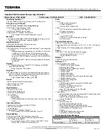
Turn over the system and remove the two screws (A) from the bottom of the left and right hinges.
Step
Size (Quantity)
Color
Torque
1~2
M2.5 x L8 (2)
Black
3.0 kgf-cm
Содержание Aspire 8735
Страница 6: ...VI ...
Страница 10: ...4 Chapter 1 System Block Diagram ...
Страница 54: ...50 Chapter 2 ...
Страница 71: ...Chapter 3 67 2 Remove the two captive screws securing the hard disk drive cover ...
Страница 81: ...Chapter 3 77 5 Disconnect the power board cable from PWCN1 connector on the system to remove it ...
Страница 94: ...90 Chapter 3 19 Disconnect the Media console cable from LEDB1 on the main board ...
Страница 112: ...108 Chapter 3 21 Remove the USB board module from the lower case ...
Страница 118: ...114 Chapter 3 13 Detach any adhesive tapes and any cable that is glued to the LCD panel ...
Страница 119: ...Chapter 3 115 14 Disconnect the FPC cable from the LCD panel ...
Страница 136: ...132 Chapter 4 F5h Boot to Mini DOS F6h Clear Huge Segment F7h Boot to Full DOS Code Beeps ...
Страница 143: ...Chapter 4 139 ...
Страница 144: ...140 Chapter 4 ...
Страница 145: ...Chapter 5 139 Motherboard Jumper and Connector Locations Chapter 5 ...
Страница 146: ...140 Chapter 5 ...
Страница 148: ...142 Chapter 5 try again NOTE The steps are only for clearing BIOS Password Supervisor Password and User Password ...
Страница 150: ...144 Chapter 5 ...
Страница 152: ...146 Chapter 6 Aspire 8735 8735G 8735ZG Series Exploded Diagram ...
Страница 170: ...158 Appendix B ...
Страница 172: ...160 Appendix C ...


