Chapter 2
35
Main
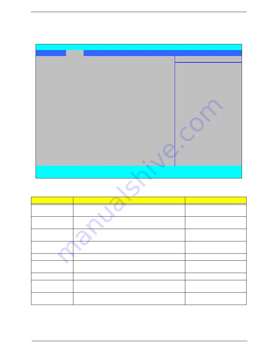
The Main screen allows the user to set the system time and date as well as enable and disable boot option
and recovery.
NOTE:
The screen above is for your reference only. Actual values may differ.
Settings in
boldface
are the default and suggested parameter settings.
Parameter
Description
Format/Option
System Time
Sets the system time. The hours are displayed with 24-
hour format.
Format: HH:MM:SS
(hour:minute:second)
System Date
Sets the system date.
Format MM/DD/YYYY
(month/day/year)
Total Memory
This field reports the memory size of the system.
Memory size is fixed to 4094 MB.
N/A
Video Memory
Shows the Video memory size. Video Memory size is
fixed to 256 MB
N/A
Quiet Boot
Select whether to display the logo screen during boot.
Option:
Enabled
or Disabled
Network Boot
Enables, disables the system boot from LAN (remote
server).
Option:
Enabled
or Disabled
F12 Boot Menu
Enables, disables Boot Menu during POST.
Option:
Disabled
or Enabled
D2D Recovery
Enables, disables the Acer D2D Recovery function
during POST by pressing
Alt-F10
.
Option:
Enabled
or Disabled
SATA Mode
Selection
Control the mode in which the SATA controller should
operate.
Option:
AHCI
or IDE Mode
Information
Main
Security
Boot
Exit
Item Specific Help
System Time
[13:04:04]
System Date
[06/04/2008]
<Tab>, <Shift-Tab>, or
<Enter> selects field.
Total Memory:
4094 MB
Video Memory:
256 MB
Quiet Boot:
[Enabled]
Network Boot:
[Enabled]
F12 Boot Menu:
[Disabled]
D2D Recovery:
[Enabled]
SATA Mode Selection:
[AHCI]
F1
Help
↑↓
Select Item
F5/F6
Change Values
F9
Setup Defaults
ESC
Exit
←→
Select Menu
Enter
Select
X
Sub-Menu
F10
Save and Exit
Phoenix SecureCore(tm) Setup Utility
Содержание Aspire 6930 Series
Страница 6: ...VI ...
Страница 10: ...X Table of Contents ...
Страница 42: ...32 Chapter 1 ...
Страница 55: ...Chapter 2 45 3 Reboot the system and key in the selected string qjjg9vy 07yqmjd etc for the BIOS user password ...
Страница 56: ...46 Chapter 2 ...
Страница 70: ...60 Chapter 3 5 Lift the HDD carrier to remove 6 Grasp the HDD connector and pull firmly to remove ...
Страница 91: ...Chapter 3 81 4 Grasp the module by the right side and lift up to remove ...
Страница 99: ...Chapter 3 89 7 Disconnect the Mic cable and remove the LCD bezel ...
Страница 110: ...100 Chapter 3 4 Replace the ten securing screws and screw caps on the LCD bezel ...
Страница 112: ...102 Chapter 3 3 Connect fan cable to the mainboard as shown ...
Страница 126: ...116 Chapter 3 7 Turn the computer over and replace the ten screws as shown ...
Страница 234: ...224 Appendix B ...
Страница 236: ...226 Appendix C ...
Страница 239: ...www s manuals com ...


