


Chapter 1
7
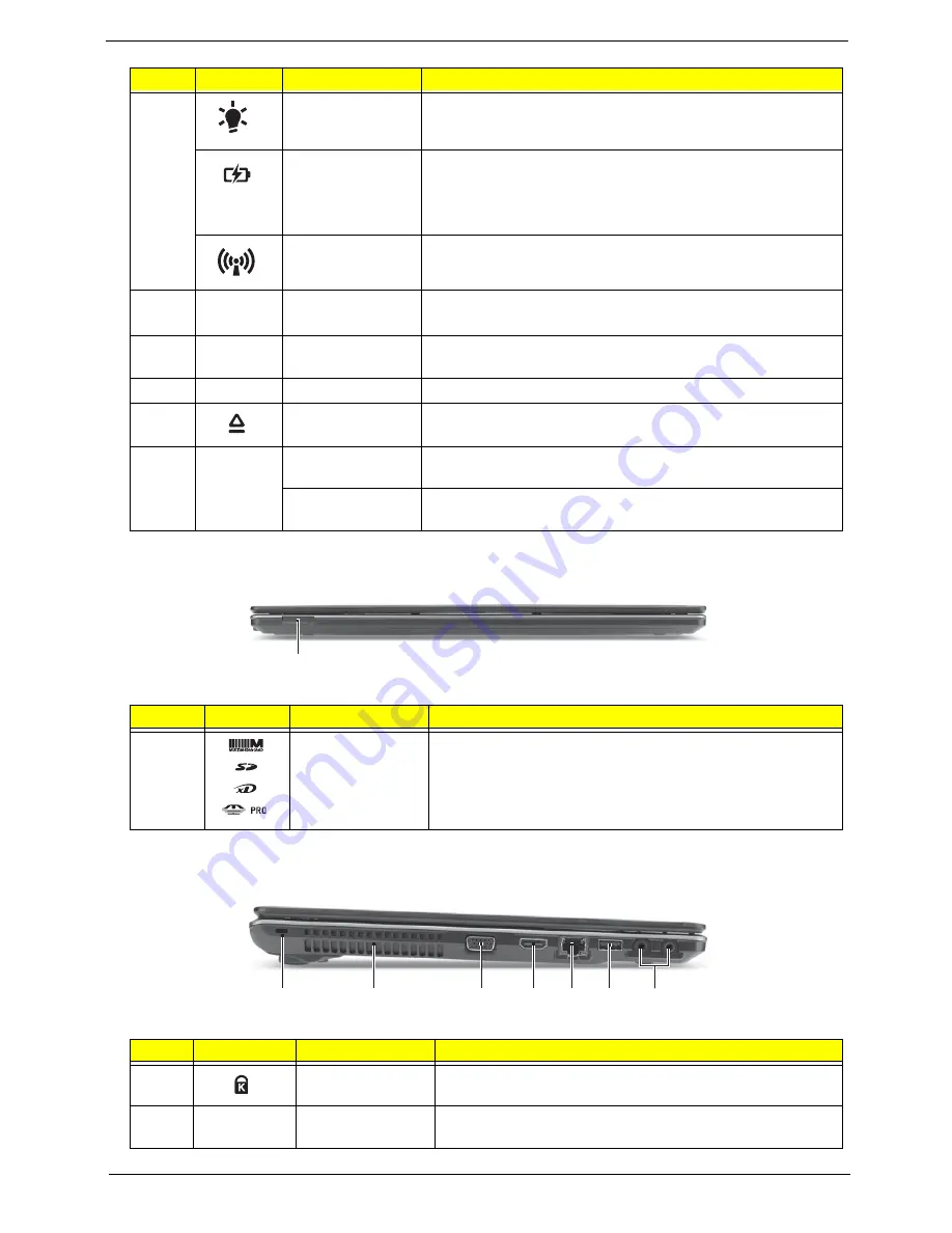
Closed Front View
Left View
8
Power
Indicates the computer’s power status.
Battery
Indicates the computer’s battery status.
1. Charging: The light shows amber when the light is
charging.
2. Fully charged: the light shows blue when in AC mode.
Communication
indicator
Indicates the computer’s wireless connectivity status.
9
Click buttons
(left, and right)
The left and right buttons function like the left and right mouse
buttons.
10
Palmrest
Comfortable support area for your hand when using the
computer.
11
Speakers
Left and right speakers deliver stereo audio output.
12
Optical drive
eject button
Ejects the optical disk from the drive.
13
P
Programmable
key
User-programmable. (only for certain models)
PowerSmart key
Puts your computer into power-saving mode. (only for certain
models)
#
Icon
Item
Description
1
Multi-in-1 card
reader
Accepts Secure Digital (SD), MultiMediaCard (MMC),
Memory Stick (MS), Memory Stick PRO (MS PRO), xD-
Picture Card (xD).
Note: Push to remove/install the card. Only one card can
operate at any given time.
#
Icon
Item
Description
1
Kensington lock
slot
Connects to a Kensington-compatible computer security
lock.
2
Ventilation slots
Enable the computer to stay cool, even after prolonged
use.
#
Icon
Item
Description
1
2
1
3
4 5 6
7
Содержание Aspire 5820T Series
Страница 6: ...VI ...
Страница 10: ...X Table of Contents ...
Страница 48: ...38 Chapter 2 ...
Страница 57: ...Chapter 3 47 4 Lift the base door out and away ...
Страница 62: ...52 Chapter 3 5 Pull the WLAN module out and away ...
Страница 64: ...54 Chapter 3 5 Pull the 3G module out and away ...
Страница 72: ...62 Chapter 3 9 Flip the keyboard over 10 Detach the keyboard FPC a Unlock the FPC b Pull the keyboard away a b ...
Страница 78: ...68 Chapter 3 4 Unlock and disconnect the switch board FFC ...
Страница 80: ...70 Chapter 3 4 Lift the power board away ...
Страница 85: ...Chapter 3 75 14 Lift the LCD module out of the assembly ...
Страница 87: ...Chapter 3 77 4 Lift away the I O board 5 Unlock and remove the I O board FFC from the mainboard ...
Страница 98: ...88 Chapter 3 Right Hinge Disassembly M2 5 3 2 86 PTN07 003 Step Screw Quantity Part No ...
Страница 100: ...90 Chapter 3 4 Pry open the bottom corners and along the bottom edge 5 Lift the bezel off the module ...
Страница 104: ...94 Chapter 3 7 Disconnect the FPC cable ...
Страница 107: ...Chapter 3 97 8 Remove the cable from the retention guides 9 Pry the antenna off the casing ...
Страница 112: ...102 Chapter 3 7 Lay the cables along the retention guides ...
Страница 118: ...108 Chapter 3 3 Press down on the bezel edge working simultaneously around the edges to the bottom ...
Страница 123: ...Chapter 3 113 2 Using a flat bladed screw driver rotate the CPU locking screw 180 clockwise to secure the CPU in place ...
Страница 127: ...Chapter 3 117 4 Connect and lock the I O card FFC to the mainboard ...
Страница 129: ...Chapter 3 119 4 Connect the Bluetooth module cable to the main board ...
Страница 133: ...Chapter 3 123 10 Press the LVDS connector left and right adhesive tabs down onto the mainboard ...
Страница 139: ...Chapter 3 129 7 Connect and lock the button board FFC ...
Страница 147: ...Chapter 3 137 4 Grasp the tab and slide the HDD firmly into the docking connector ...
Страница 150: ...140 Chapter 3 4 Push the ODD completely into the bay until flush with the lower cover ...
Страница 153: ...Chapter 3 143 Replace the Dummy Card Push the dummy card into the slot until it clicks into place ...
Страница 154: ...144 Chapter 3 ...
Страница 172: ...162 Chapter 4 ...
Страница 176: ...166 Chapter 5 ...
Страница 190: ...180 Chapter 6 ...
Страница 260: ...250 Appendix A ...
Страница 266: ...256 ...


