


146
Chapter 4
Power On Issue
If the system doesn’t power on, perform the following actions one at a time to correct the problem. Do not
replace non-defective FRUs:
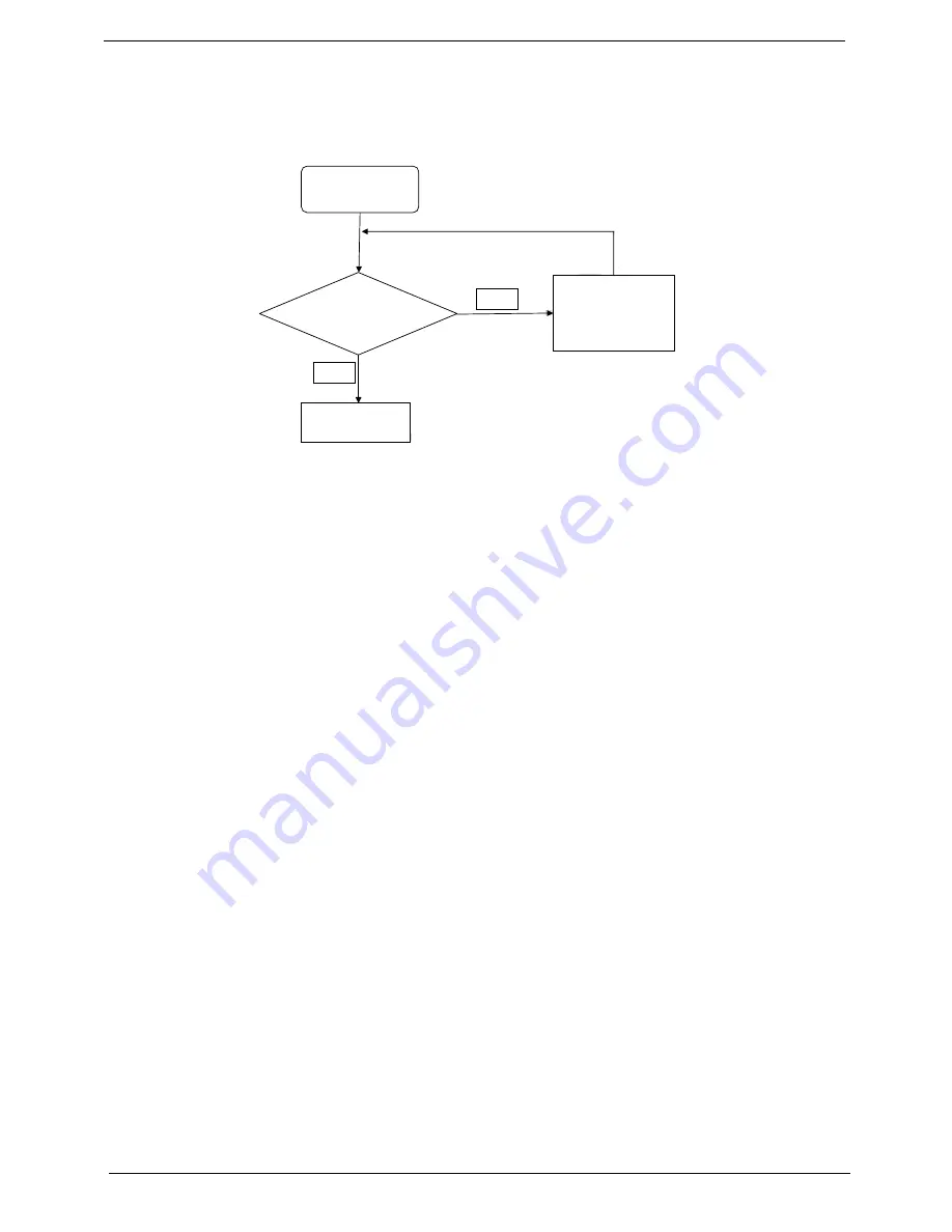
Computer Shuts down Intermittently
If the system powers off at intervals, perform the following actions one at a time to correct the problem.
1.
Check the power cable is properly connected to the computer and the electrical outlet.
2.
Remove any extension cables between the computer and the outlet.
3.
Remove any surge protectors between the computer and the electrical outlet. Plug the computer directly
into a known good electrical outlet.
4.
Remove all external and non-essential hardware connected to the computer that are not necessary to
boot the computer to the failure point.
5.
Remove any recently installed software.
6.
If the Issue is still not resolved, see “Online Support Information” on page 255.
Check
AC/Battery
Swap AC/Battery
try
NG
OK
Swap M/B
Start
Содержание Aspire 5820T Series
Страница 6: ...VI ...
Страница 10: ...X Table of Contents ...
Страница 48: ...38 Chapter 2 ...
Страница 57: ...Chapter 3 47 4 Lift the base door out and away ...
Страница 62: ...52 Chapter 3 5 Pull the WLAN module out and away ...
Страница 64: ...54 Chapter 3 5 Pull the 3G module out and away ...
Страница 72: ...62 Chapter 3 9 Flip the keyboard over 10 Detach the keyboard FPC a Unlock the FPC b Pull the keyboard away a b ...
Страница 78: ...68 Chapter 3 4 Unlock and disconnect the switch board FFC ...
Страница 80: ...70 Chapter 3 4 Lift the power board away ...
Страница 85: ...Chapter 3 75 14 Lift the LCD module out of the assembly ...
Страница 87: ...Chapter 3 77 4 Lift away the I O board 5 Unlock and remove the I O board FFC from the mainboard ...
Страница 98: ...88 Chapter 3 Right Hinge Disassembly M2 5 3 2 86 PTN07 003 Step Screw Quantity Part No ...
Страница 100: ...90 Chapter 3 4 Pry open the bottom corners and along the bottom edge 5 Lift the bezel off the module ...
Страница 104: ...94 Chapter 3 7 Disconnect the FPC cable ...
Страница 107: ...Chapter 3 97 8 Remove the cable from the retention guides 9 Pry the antenna off the casing ...
Страница 112: ...102 Chapter 3 7 Lay the cables along the retention guides ...
Страница 118: ...108 Chapter 3 3 Press down on the bezel edge working simultaneously around the edges to the bottom ...
Страница 123: ...Chapter 3 113 2 Using a flat bladed screw driver rotate the CPU locking screw 180 clockwise to secure the CPU in place ...
Страница 127: ...Chapter 3 117 4 Connect and lock the I O card FFC to the mainboard ...
Страница 129: ...Chapter 3 119 4 Connect the Bluetooth module cable to the main board ...
Страница 133: ...Chapter 3 123 10 Press the LVDS connector left and right adhesive tabs down onto the mainboard ...
Страница 139: ...Chapter 3 129 7 Connect and lock the button board FFC ...
Страница 147: ...Chapter 3 137 4 Grasp the tab and slide the HDD firmly into the docking connector ...
Страница 150: ...140 Chapter 3 4 Push the ODD completely into the bay until flush with the lower cover ...
Страница 153: ...Chapter 3 143 Replace the Dummy Card Push the dummy card into the slot until it clicks into place ...
Страница 154: ...144 Chapter 3 ...
Страница 172: ...162 Chapter 4 ...
Страница 176: ...166 Chapter 5 ...
Страница 190: ...180 Chapter 6 ...
Страница 260: ...250 Appendix A ...
Страница 266: ...256 ...


