2-16
System Utilities
Using DMI Tools
0
The
DMI
(Desktop Management Interface)
Tool
copies BIOS information to EEPROM
(Electrically Erasable Programmable Read-Only Memory). Used in the DMI pool for hardware
management.
LAN EEPROM Utility
0
LAN EEPROM Utility enables to change the MAC address.
Perform the following steps to use the LAN EEPROM Utility:
1. Create a DOS bootable USB HDD.
2. Copy the contents of the MAC folder to the HDD and remove the HDD form the computer.
3. Reboot the computer and press
F2
during the boot sequence to enter the setup menu.
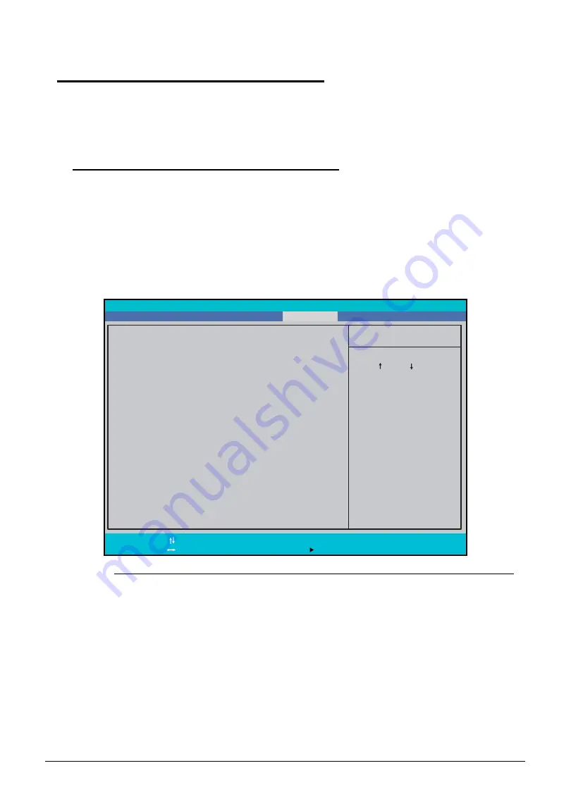
4. Select the Boot menu item and move the entry “USB HDD” to the first position.
Figure 2-15.
BIOS Boot
5. Connect the USB HDD and reboot the computer.
6. At the command prompt, navigate to the MAC folder.
7. Execute the <
MAC.BAT
> file.
8. At prompt type in MAC address.
9. Press
Enter
.
10. Reboot when the process has completed.
I t e m S p e c i f i c H e l p
U s e < > o r < > t o
s e l e c t a d e v i c e , t h e n
p r e s s < F 6 > t o m o v e i t
u p t h e l i s t , o r < F 5 >
t o m o v e i t d o w n t h e
l i s t . P r e s s < E s c > t o
e s c a p e t h e m e n u .
B o o t P r i o r i t y O r d e r :
F1
Esc
H e l p
E x i t
S e l e c t I t e m
S e l e c t M e n u
C h a n g e Va l u e s
S e l e c t S u b - M e n u
F5/F6
Enter
F9
F10
S e t u p D e f a u l t s
S a v e a n d E x i t
2 : ATA P I C D / D V D : M AT S H I TA B D - C M B U J 1 4 1 A J
3 : U S B F D D :
4 : N e t w o r k B o o t : B R C M M B A S l o t 0 2 0 0 v 1 4 . 6 . 9
5 : U S B H D D :
6 : U S B C D R O M :
1 : H D D 0 : TO S H I B A M K 7 5 5 9 G S X P
B o o t
E x i t
M a i n
I n f o r m a t i o n
S e c u r i t y
P h o e n i x S e c u r e C o r e Ti a n o S e t u p
Содержание Aspire 5560
Страница 1: ... Aspire 5560 SERVICEGUIDE ...
Страница 10: ...6 ...
Страница 11: ...CHAPTER 1 Hardware Specifications ...
Страница 14: ...1 4 ...
Страница 34: ...1 24 Hardware Specifications and Configurations System Block Diagram Figure 1 12 System Block Diagram ...
Страница 52: ...1 42 Hardware Specifications and Configurations ...
Страница 53: ...CHAPTER 2 System Utilities ...
Страница 69: ...CHAPTER 3 Machine Maintenance ...
Страница 72: ...3 4 ...
Страница 81: ...Machine Maintenance 13 5 Pry the ODD bezel off the module Figure 3 10 ODD Bezel ...
Страница 86: ...18 Machine Maintenance 4 Remove the WLAN module from the slot Figure 3 18 WLAN Module ...
Страница 97: ...Machine Maintenance 29 4 Lift the speakers from the upper cover Figure 3 38 Speaker Screws ...
Страница 107: ...Machine Maintenance 39 4 Remove the thermal module from the mainboard Figure 3 54 Thermal Module ...
Страница 112: ...44 Machine Maintenance 6 Remove the LCD module from the lower case Figure 3 62 LCD Module ...
Страница 131: ...Machine Maintenance 63 3 Secure the bezel with the two screw covers Figure 3 93 LCD Bezel Screw Covers ...
Страница 134: ...66 Machine Maintenance 5 Position the DC input cable on the lower case Figure 3 98 DC Input Cable ...
Страница 167: ...CHAPTER 4 Troubleshooting ...
Страница 198: ...4 32 Troubleshooting ...
Страница 199: ...CHAPTER 5 Jumper and Connector Locations ...
Страница 205: ...CHAPTER 6 FRU List ...
Страница 206: ...6 2 Aspire 5560 Exploded Diagrams 6 4 Main Assembly 6 4 LCD Assembly 6 5 FRU List 6 7 ...
Страница 220: ...6 16 FRU Field Replaceable Unit List ...
Страница 221: ...CHAPTER 7 Model Definition and Configuration ...
Страница 222: ...7 2 Aspire 5560 7 3 ...
Страница 223: ...Model Definition and Configuration 7 3 Model Definition and Configuration Aspire 5560 0 ...
Страница 224: ...7 4 Model Definition and Configuration ...
Страница 225: ...CHAPTER 8 Test Compatible Components ...
Страница 226: ...8 2 Microsoft Windows 7 Environment Test 8 4 ...
Страница 236: ...8 12 Test Compatible Components ...
Страница 237: ...CHAPTER 9 Online Support Information ...
Страница 238: ...9 2 ...
Страница 240: ...9 4 Online Support Information ...


