Chapter 1
11
Indicators
The computer has several easy-to-read status indicators. The front panel indicators are visible even when the
computer cover is closed.
NOTE:
1.
Charging:
The light shows amber when the battery is charging. 2.
Fully charged:
The light shows
green when in AC mode.
Easy-Launch Buttons
Located above the keyboard are application buttons. These buttons are called easy-launch buttons. They are:
WLAN, Internet, email, Bluetooth, Arcade and Acer Empowering Technology.
The mail and Web browser buttons are pre-set to email and Internet programs, but can be reset by users. To
set the Web browser, mail and programmable buttons, run the Acer Launch Manager.You can access the
Launch Manager by clicking on Start, All Programs, and then Launch Manager to start the application.
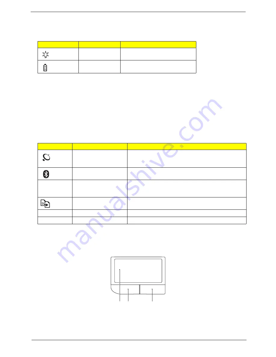
Touchpad basics (with two-click buttons)
The following items show you how to use the touchpad with two-click buttons.
•
Move your finger across the touchpad
(1)
to move the cursor.
•
Press the left
(2)
and right
(3)
buttons located beneath the touchpad to perform selection and execution
functions. These two buttons are similar to the left and right buttons on a mouse. Tapping on the
touchpad is the same as clicking the left button.
Icon
Function
Description
Power
Indicates the computer's power
status.
Battery
Indicates the computer's battery
status.
Icon
Function
Description
Wireless LAN
communication button/
indicator
Enables/disables the wireless LAN function. Indicates the
status of wireless LAN communication.
Bluetooth communication
button/indicator
Enables/disables the Bluetooth function. Indicates the status
of Bluetooth communication. (only for certain models)
3G
3G WWAN
communication button/
indicator
Enables/disables the 3G WWAN function. Indicates the
status of 3G WWAN communication. (only for certain
models)
Backup key
Launches Acer Backup Management for three-step data
backup.
VOL+
Volume up
Increases the sound volume.
VOL-
Volume down
Decreases the sound volume.
1
2
3
Содержание Aspire 5536
Страница 6: ...VI...
Страница 12: ...4 Chapter 1 System Block Diagram For Aspire 5738G 5738ZG 5738Z 5738 5338 Series...
Страница 13: ...Chapter 1 5 For Aspire 5536 5536G 5236 Series...
Страница 34: ...26 Chapter 1...
Страница 49: ...Chapter 2 41...
Страница 50: ...42 Chapter 2...
Страница 82: ...74 Chapter 3 14 Remove the USB board module from the lower case...
Страница 93: ...Chapter 3 85 19 Using a flat screwdriver turn the CPU socket latch counter clockwise to release the CPU...
Страница 104: ...96 Chapter 3...
Страница 116: ...108 Chapter 4 F5h Boot to Mini DOS F6h Clear Huge Segment F7h Boot to Full DOS Code Beeps...
Страница 132: ...124 Chapter 6 Aspire 5738G 5738ZG 5738Z 5738 5338 Series and Aspire 5536 5536G 5236 Series Exploded Diagram...
Страница 178: ...Appendix A 170 Model Definition and Configuration Appendix A...
Страница 224: ...Appendix A 216...
Страница 228: ...220 Appendix B...
Страница 230: ...222 Appendix C...


